Part Type: Straight Pipe
Rules for the creation of individual Plant Engineering parts
|
Position of connecting points and determination of insertion lengths for various connection types |
|||
|---|---|---|---|
|
Connection for butt welding |
Flange connection |
Connecting nipple for |
Connecting socket for |
|
|
|
|
|
| a = Insertion length dimension (e.g. L, L1 etc.) |
a = Insertion length dimension (e.g. L, L1 etc.) |
a = Insertion length dimension (e.g. L, L1 etc.) |
a = Insertion length dimension (e.g. L, L1 etc.) |
Named isolated points
|
Designation |
Purpose |
Comment |
Position in coordinate system |
|---|---|---|---|
|
! |
Connecting point |
Fitting point |
in origin (0,0,0) |
|
2 |
Connecting point |
|
X = 0, Y = 0, Z > 0 |
Required attributes for entries into database or catalogue
The entering of attribute values and the part type selection should be performed using the PAA Editor.
Values need to be entered for at least the following attributes:
|
Attribute |
Designation |
|||||||||||||||||||||||
|---|---|---|---|---|---|---|---|---|---|---|---|---|---|---|---|---|---|---|---|---|---|---|---|---|
|
BENENNUNG |
Designation of part |
|||||||||||||||||||||||
|
NORMBEZEICHNUNG |
Standard designation of the part. An entry is mandatory, even if the part corresponds to no standard. |
|||||||||||||||||||||||
|
BELIEBIG_TEILBAR |
Arbitrarily divisible; indicates whether a cutting to length of the pipe is permissible |
|||||||||||||||||||||||
|
LIEFERLAENGE |
Supplied length in m (!) |
|||||||||||||||||||||||
|
|
|
|||||||||||||||||||||||
|
NENNWEITE |
Nominal diameter, Connection “!“ and “2“ |
|||||||||||||||||||||||
|
BESTELLVERMERK |
Order note, individual content |
|||||||||||||||||||||||
|
|
|
|||||||||||||||||||||||
|
Additionally (only if the corresponding standard uses nominal diameters in inches): |
||||||||||||||||||||||||
|
NPS_INCH |
Nominal diameter (inches) (e.g. 1 1/2‘', the '' consists of two '' characters), Connection“!“ and “2“ |
|||||||||||||||||||||||
|
|
|
|||||||||||||||||||||||
|
These parameters are to be considered for all connection types except for flange connections. For connecting sockets they refer to the pipe to be inserted: |
||||||||||||||||||||||||
|
D_AUSSEN |
Outer diameter, Connection“!“ and “2“ |
|||||||||||||||||||||||
|
WANDDICKE |
Wall thickness, Connection“!“ and “2“ |
|||||||||||||||||||||||
|
|
|
|||||||||||||||||||||||
|
ANSCHLUSSART
ANSCHLUSSART2 |
Connection type , Connection“!“ (and “2“) If you want both pipe ends to have the same connection type it will suffice to specify a value for the ANSCHLUSSART attribute. If you want the two pipe ends to have different connection types, the connection type for Connection 1 must be specified for the ANSCHLUSSART attribute, and the connection type for Connection 2 for the ANSCHLUSSART2 attribute. If you want to create a new feature variant of a straight pipe with different connection types, the part must be constructed in such a way that the value of the attribute ANSCHLUSSART is smaller than the value of the attribute ANSCHLUSSART2. Example: Let us assume that you require a pipe that can be butt-welded at one end, and has a screwed socket at the other end. The connection type for butt-welded connections is 10000, the one for screwed sockets is 32000. This means that Connection 1 (Point designation "!") is required for the welded connection (ANSCHLUSSART = 10000) and Connection 2 (point designation "2") is required for the screwed connection (ANSCHLUSSART2 = 32000). |
|||||||||||||||||||||||
|
Possible values of the attribute ANSCHLUSSART (CONNECTION_TYPE):
The last character (x) provides information about the meaning of the supplement: 0 =No supplement 2 = The supplement consists of connection number, part type, ID, and standard of the part to be connected The prefixed connection number indicates the connection with which the auxiliary part is to be attached to the current connection.
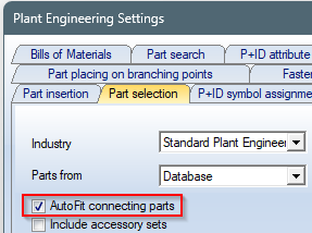
If straight pipes are to be inserted with the loose flange from the connection attributes, the AutoFit connecting parts option must be activated on the Part selection tab of the Plant Engineering Settings dialogue window.
|
||||||||||||||||||||||||
 Please also read the information given in the paragraphs
