3-D Standard > Process with sketch > Subt. > Divide with sketch
With this function you divide a part based on a planar sketch. Each line of the sketch is a section line that divides the part into two section regions. Connected lines are treated as one line. This means, for example, that a sketch consisting of three connected lines also divides a part into two cutting regions. Each cutting region can consist of several sections, whereby the number of sections is determined by the actual number of lines.
The following image shows parts that have been divided with a clearance - a cylinder, a cuboid and a sheet metal part.
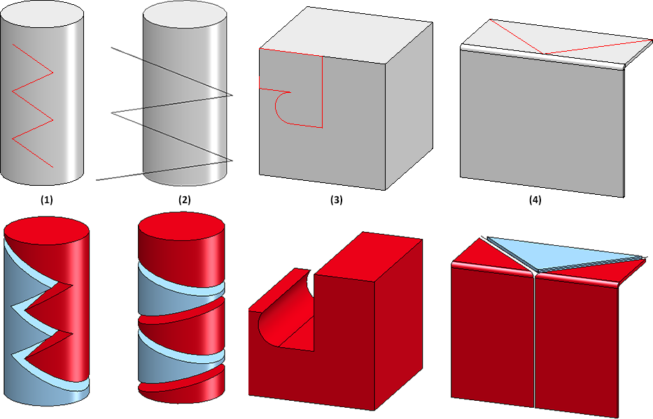
(1) The sketch consists of five connected lines, none of which extend beyond the part. This results in two segments.
(2) Here the sketch extends beyond the edge of the cylinder. However, there are two parts but they consist of several parts.
(3) The sketch is closed and two sketch lines lie exactly on the edges of the cuboid. In this case, one area of the cuboid is cut away completely and no additional part is created. (In this case, a material subtraction would also have led to the goal).
(4) Two parts are created, whereby the red part consists of two segments.
Topics:

The dialogue window
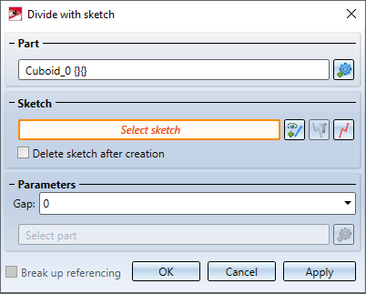
After calling the function, the Divide with sketch dialogue window is displayed.
Part
The system will always choose the active part for processing, with the name being displayed under Part. If the function is called while an invalid part is active (e.g. a dummy part), the text Select part will be displayed instead of the part name. In this case, you can select the part to be processed directly in the ICN or in the drawing. If you want to process a part other than the one displayed, click on the  symbol and select the desired part in the ICN or in the drawing.
Sketch
Select a sketch for the division of the part. You have the following options:
|
|
Select sketch Click on the icon to subsequently select another sketch. After calling up the function, the sketch can also be selected directly in your drawing. |
|
|
Process sketch This function allows you to modify a previously selected sketch. For this purpose, the Process sketch dialogue window is displayed. Then change the sketch as desired and click Apply sketch in the dialogue window. The dialogue will continue with the modified sketch. |
|
|
New sketch in plane With this function you can create a new sketch that will be used to create the solid. Create the desired sketch and then click Apply sketch. The dialogue continues with the new sketch. |


If you want to delete the sketch after dividing, activate the corresponding checkbox.
After selecting the sketch, a preview of the division is displayed immediately.
Parameter
If desired, specify a Gap (clearance) under Parameters. The preview is updated automatically.
One of the resulting parts is highlighted red in the preview. This part is the "leading part" and is automatically determined by HiCAD. The leading part receives the original feature and the main feature of the division is assigned to it. This part can consist of several segments. This depends on whether the sketch lines are connected or not.
If you want to select another part as the leading part, click on the symbol and select the part. In the preview the colour of the parts changes.
Break up referencing
If the original part is referenced, the referencing can be broken up by deactivating the checkbox. When breaking up, an existing HELiOS document and article master at the original part is also deleted. If the checkbox is active, the referencing is assigned to the leading part. This also applies to a HELiOS document/article master existing at the starting part - the other parts created are not referenced.
The division is executed by clicking OK. Alternatively, you can also press the middle mouse button. The dialogue window will be closed after dividing.
It is also possible to execute the division by clicking Apply but the dialogue window will remain open in this case. You can then process further parts. The function can be terminated by using the middle mouse button.
![]() Please note:
Please note:
- Alternatively, you can call the function via the context menu for parts.
- Sub-parts are not considered in the function. Sheet metal parts are an exception.
- The sketch lines can also overlap.
The Divide feature
Each resulting segment is a separate part in the part structure - on the same hierarchic level as the original part and with the same name. The leading part receives the original feature of the original part and a feature called Divide with sketch. This is the main feature. All other parts receive a feature with the name from division. These are the dependent features.
If the main feature is selected in the ICN, then, in addition to the original part, all associated segments in the drawing will also be highlighted in colour. This also applies vice versa.
The division can be edited subsequently by double-clicking on the main feature or on a dependent feature. All segments will be recalculated accordingly.
The following should be noted:
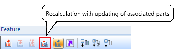
If you apply changes, for example to the gap, directly in the feature log, the calculation and updating of the division will be performed directly. If variables are used instead and these are changed, the recalculation with updating of the division must be triggered manually. To do this, use the Recalculation with updating of associated parts  function in the toolbar of the feature window in the ICN.
If the main feature Divide along direction is activated / deactivated, the associated features from division are also automatically activated / deactivated. At the same time the dependent parts will be recalculated accordingly, i.e.:
- If the main feature is deactivated, the original part will be restored and the segments will become dummy parts.
- If the main feature is activated, all segments will be restored.
Please note:
If the sketch region for the main feature cannot be found again, this is documented as an error on the feature.
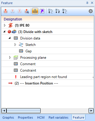
Possible reasons for the omission of the main feature region are:
- The region is deleted from the sketch
- The section is empty
Examples
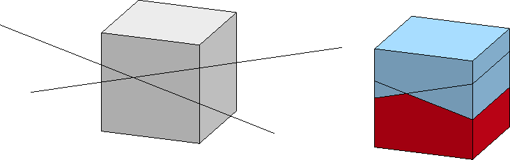
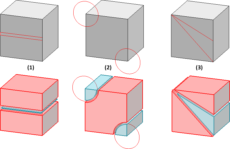
Example 1:
The image shows a cuboid with three different sketches and the resulting division. In all cases, two parts are created. In (1) and (3) the "leading part" consists of two segments, in case (2) of one segment.
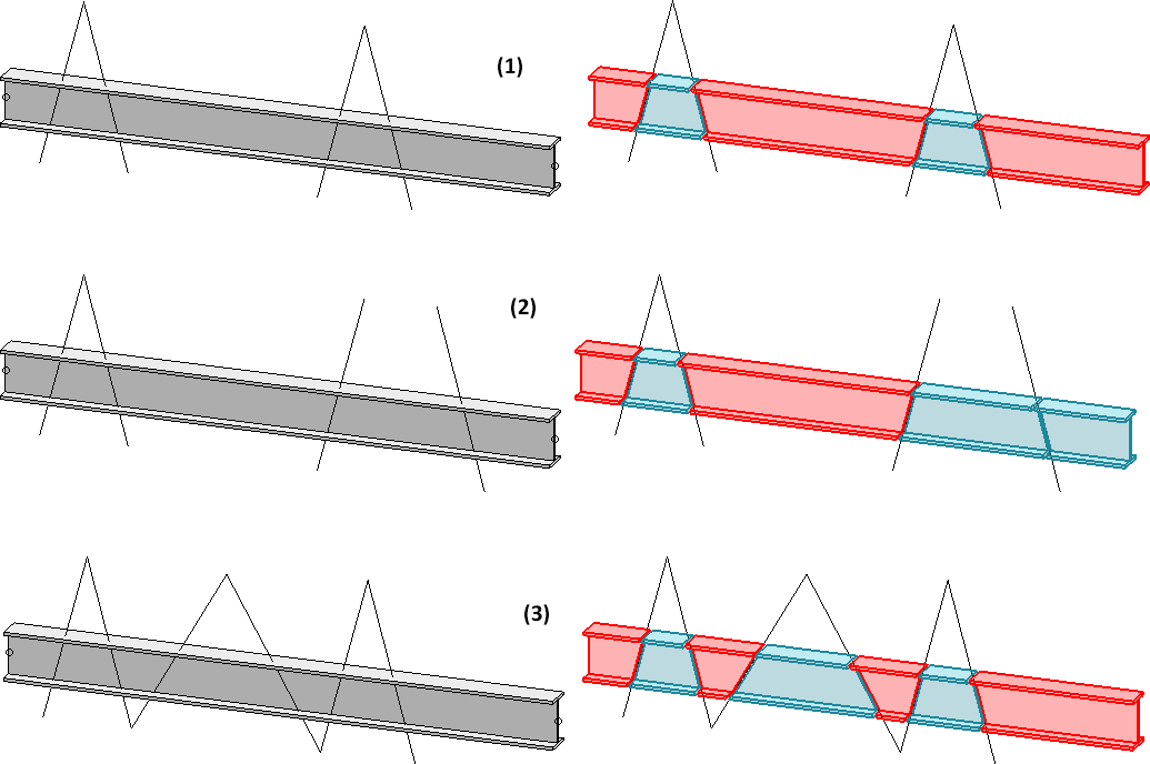
Example 2:
The following image shows a divided profile.
(1) Three parts are created, whereby the red part consists of three segments.
(2) Four parts are created, whereby the red component consists of two segments.
(3) Two parts with four (red) and three (blue) segments are produced.
The "leading part" (marked red when the function is executed) is assigned the main feature Divide with sketch. With this feature the sketch can be edited later and the gap can be changed. All other created parts are assigned the feature from division.
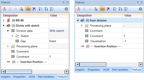
Double-click on one of the features to start the dialogue.
![]() Please note:
Please note:
If a sketch has HCM dimensions, they are transferred to the feature as parametric dimensions. If a parametric dimension is changed in the graphics window, this change will adjust the associated HCM dimension.

Sketch Function (3-D) • The "Process with Sketch" Dialogue Window (3-D)