Cam Connection

Cams and cam processings
The cam creation creates cams on one part and slots (holes) in which these cams fit on another part. Cams can be applied to almost all types of parts, including thin-walled solids. You can specify how the cams and corresponding slots should look and how they should be arranged along the selected parts. For example, individual cams can be places freely , the cams can also be distributed unevenly and they can have different edge distances on the sides.
The following functions are available:
|
|
Cams With this function, a part is provided with cams. |
|
|
Cam processing
|
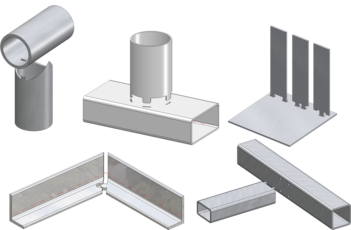
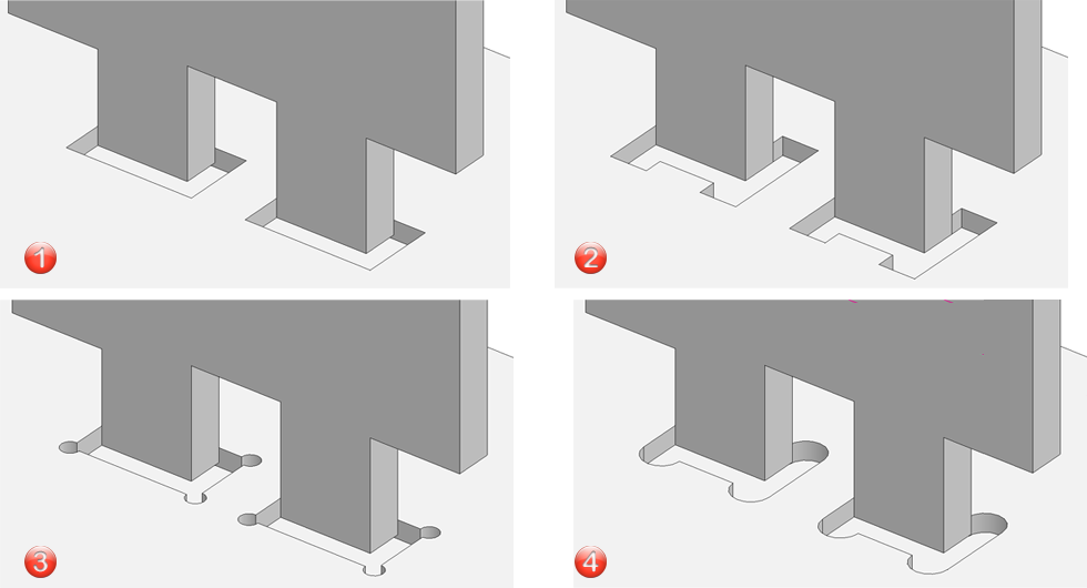
The image shows different cams and the corresponding standard processings.
Generate cams
3-D Standard > Standard Processings > Bore > Cams 
With this function you can add cams to a part. The dialogue window is displayed for this purpose:
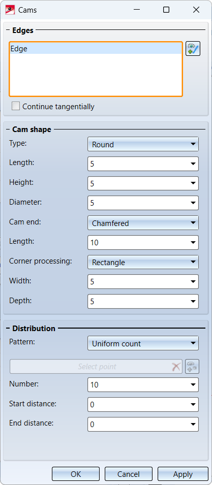
Selecting the edges
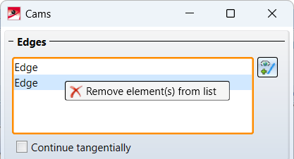
In the Edges area, select the edge where the cams are to be installed. You can select multiple edges here, but they must belong to the same part. To remove an edge from the selection, right-click on the corresponding list entry and select the function Remove element(s) from the list. To subsequently add more edges to the selection, click on  and select the edges.
The settings of the dialogue window always apply to the edge marked in the list.
If an edge has tangentially connecting edges, these can be selected in one step by activating the Continue tangentially checkbox. These are then considered as one edge in the list.
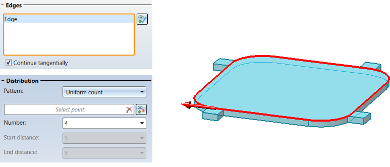
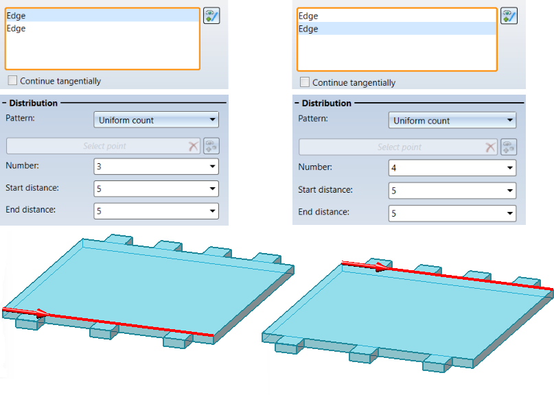
When selecting edges, note that the cams are inserted in the direction shown in the preview. That is, the direction depends on the cursor setting during the selection.
The direction in which the cam points is always perpendicular to the surface to which it is attached.
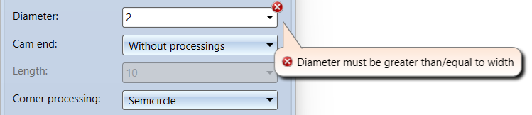
The shape of the cams
In the Cam shape area you define the appearance and size of the cam. These are the cam type, cam end and corner processing.
|
Cam type |
Cam end |
Corner processing |
|---|---|---|
|
Set implementation at cam end
|
Appearance of the corners of the cam on the edge:
|
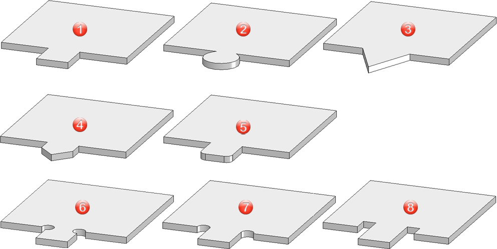
The following image shows several examples.
|
|
Cam type |
Cam end |
Corner processing |
|
Cam type |
Cam end |
Corner processing |
|---|---|---|---|---|---|---|---|
|
1 |
Straight line |
Without processings |
Without processings |
5 |
Straight line |
Filleted |
Without processings |
|
2 |
Round |
Without processings |
Without processings |
6 |
Straight line |
Without processings |
Drilled |
|
3 |
Triangular |
Without processings |
Without processings |
7 |
Straight line |
Without processings |
Semicircle |
|
4 |
Straight line |
Chamfered |
Without processings |
8 |
Straight line |
Without processings |
Rectangle |
Cam distribution
The number of cams to be inserted and the insertion pattern are defined here. Two procedures are possible:
- Uniform count or
- Individual distances.
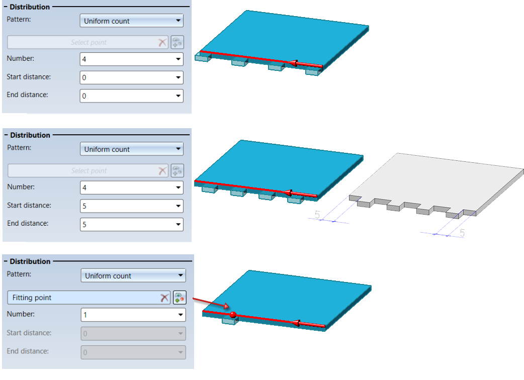
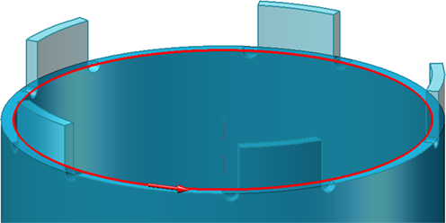
Uniform count
With this method, the cams are distributed evenly on the edge after entering the number. As long as the edges do not close - for example with circles or with tangential continuation - the distance of the first cam to the start point and the distance of the last cam to the end point of the edge can be entered for a number > 1. If no distance is entered, the first cam will start at the start point of the edge and the last cam will end at the end point of the edge. If only one cam is installed, it will be centred on the edge. However, you have the option of selecting a different control point. To do this, click on  and specify the point in the drawing.
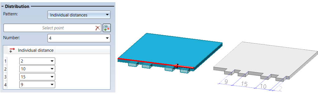
Individual distances
Here you determine the distance of the first cam to the start point of the edge and the distances from the start point of a cam to the start point of the next cam.
Insertion
As soon as cams can be generated based on the current inputs, a graphical preview will be displayed, e.g.
 .
.
When you click Apply, the cams are inserted as shown in the preview. The dialogue window remains open so that you can insert further cams without calling the function again. This way you have the possibility to insert different cams at the different edges without leaving the dialogue window. Click OK to close the dialogue window after the cams have been inserted.
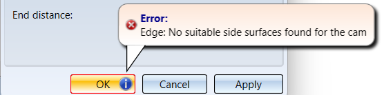
If it is not possible to insert the cams with the current settings, this will be indicated in the dialogue window by the symbol  on the OK button. In addition, the selection or input causing the problem is also marked with
  in the dialogue. If you point the cursor to one of the symbols, a corresponding explanation will be displayed, e.g.
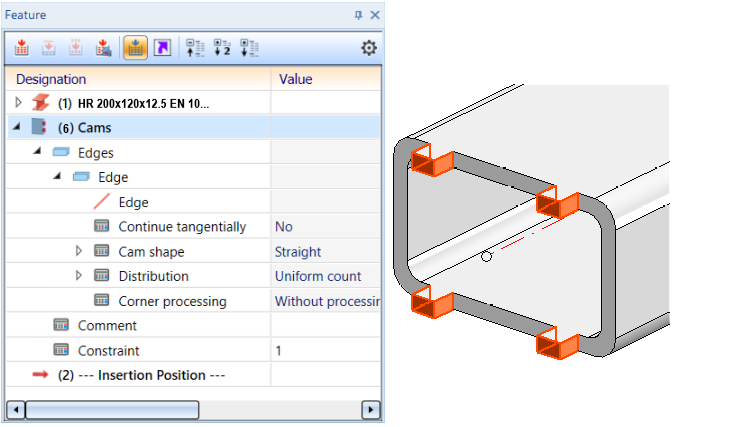
Each time you click Apply, a Cams feature will be created for the currently selected edges. Cams can be changes subsequently via this feature - either directly in the Feature log or after double-clicking on the Cams feature in the Cams dialogue window.
Generate cam processings
3-D Standard > Standard Processings > Bore > Cam processing 
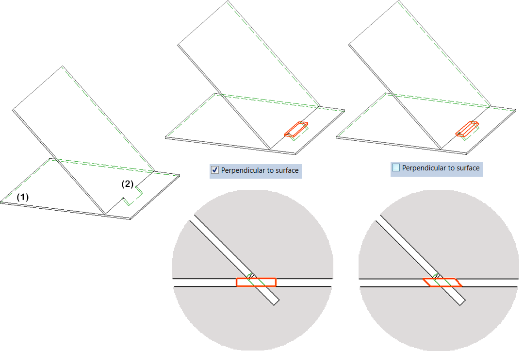
This function creates the processings on a part (2), i.e. the bores and cut-outs into which the cams of a donor (1) fit.
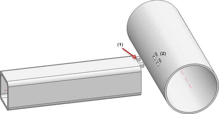
After calling the function, the dialogue window shown will be displayed:
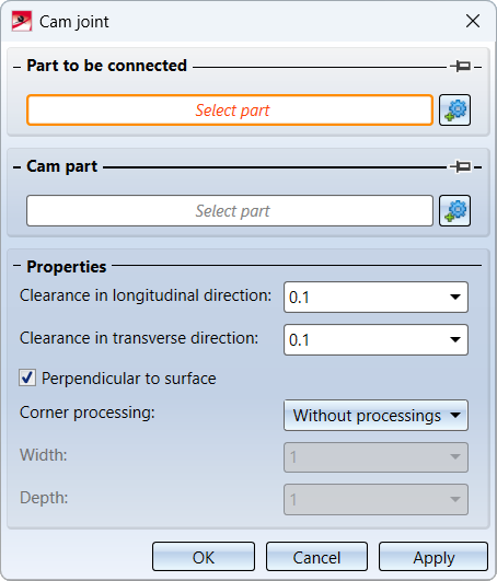
To create standard processings on a part, select the corresponding part and the part with cams in the drawing or in the ICN. The names of the selected parts will be displayed under Part to be connected or Cam part. You can correct the selection by clicking on the  icon.
icon.
In the Properties area, you can specify additional parameters for the processings:
|
Clearance |
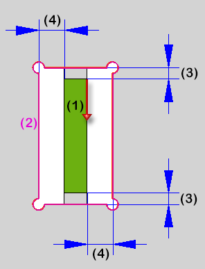
The clearance, i.e. the distance between the cam edges and the edges of the cam processing, can be entered for the longitudinal and transverse direction of the processing. The longitudinal direction is the cam direction, the transverse direction is the left/right side of the cam. Example:
(1) Cam with direction, (2) Cam processing, (3) Clearance in longitudinal direction, (4) Clearance in transverse direction |
|
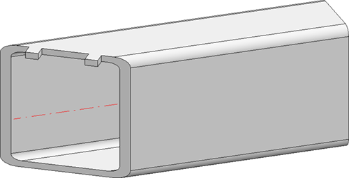
Perpendicular to surface |
By activating this checkbox, you can specify that the processing is generated perpendicular to the surface to the part. In the following image, the cam processing to sheet (2) has been generated in sheet (1).
|
|
Corner processing |
As with the cams, various corner processings are possible:
|
If it is possible to generate the cam processings, this will be visualised directly in the preview.
When you click Apply, the cam processings are inserted as shown in the preview. The dialogue window remains open so that you can insert further cam processings without calling the function again. Click OK to close the dialogue window after the cam processings have been inserted.
A Cam processing feature is created for cam processings. If the associated cam changes, the cam processing can be updated by recalculating the feature.
The pin symbol
The  symbol has a special meaning when you apply and then insert further cam processings. If this symbol is clicked, the symbol display will change to
  . If this setting is active, HiCAD will remember the part to be connected or the part with cams after the application. This is then preset in the dialogue window.
Example:
Cam processings are to be generated on multiple parts, all of which refer to the same cam part.
After calling the function, select the part to be connected and then the cam part. Then set the pin symbol to and click Apply. The standard processings will be generated and the dialogue window will remain active, with the previously selected cam part now preset. This means that you now only have to select the parts to be connected.
