3-D Dimensioning + Text > Symbols > Edge state 
Workpieces are not infrequently produced with unwanted burrs or undercuts (missing material). You can use the Edge state function to describe the condition the inner and outer edges of a workpiece according to ISO 13715.
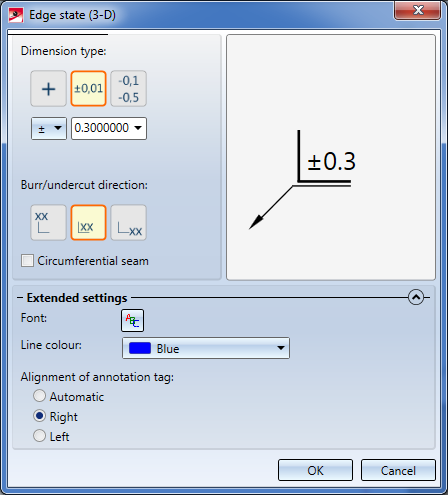
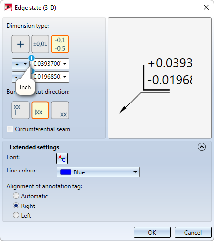
When you call the function, the Edge state dialogue window will be displayed:
Dimension type
Click on the desired symbol to select the dimension type:
|
|
Unspecified burr height/undercut size |
|
|
A limit value |
|
|
Upper and lower deviation limit |


For each of the dimension types you need to choose a positive or negative sign from the listbox. This positive or negative sign determines whether a material surplus or missing material was found. They have the following meaning for the edges:
|
|
Inner edge |
Outer edge |
|---|---|---|
|
+ |
Transition |
Burr |
|
- |
Undercut |
No burr |
|
± |
Sharp-edged (transition or undercut) |
Sharp-edged (with or without burr) |
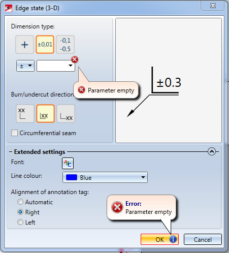
Depending on the dimension type, limit values need to be specified. These values indicate the tolerance for burrs or edge transitions in the drawing. If these specifications are missing, this will be indicated accordingly in the dialogue window:
Burr/undercut direction
The burr/undercut direction will be determined by the position of the dimension text on the edge symbol:
|
|
Vertical burr/undercut direction |
|
|
Any burr/undercut direction |
|
|
Horizontal burr/undercut direction |


Circumferential seams can be marked with a circle symbol. For this to happen, the checkbox needs to be activated.
Extended settings
Click the  and
and  symbols at the bottom of the dialogue window to open the Extended settings section. Here you can specify the alignment of the annotation tag, the font and the line colour.
The pre-settings for the designation of edge states can be specified in the Configuration Editor under Drawing > Annotations > Edge state. This also applies to the dimension unit of the edge state. It is independent of the dimension unit of the drawing.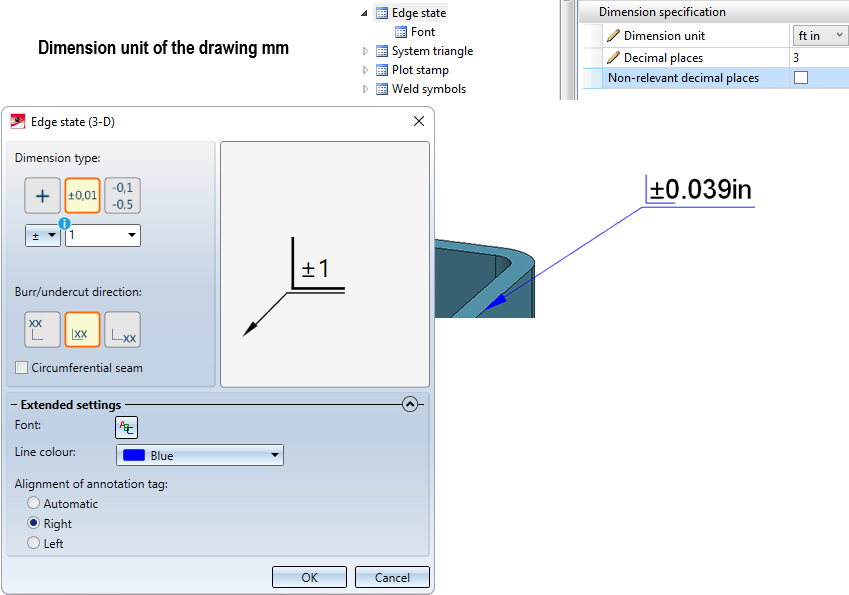
After completing your settings, confirm with OK. Then, choose the edge to be annotated, or select a point and determine the inflexion point of the leader line.
The Edge state dialogue window will appear again, allowing you to annotate further edges. Click Cancel to end the function.
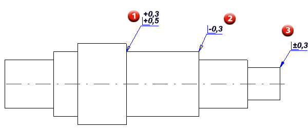
(1) Inner edge - Transition (from 0,3 to 0,5)
(2) Outer edge, no burrs (from 0 to 0,3)
(3) Outer edge, sharp (with or without burrs, from 0 to 0,3)
Please note:
The dimension unit selected for the edge state in the Configuration Editor applies to subsequently created annotations. Annotations that already exist in a drawing and that were created with different settings will not be automatically converted. When editing these annotations, the corresponding values will be marked in the dialogue.
The dimension unit is not output if millimeters "mm" is selected for both the unit of length of the drawing and the dimension unit of the edge state.


Dimensioning (3-D) • Dimensioning - Procedure (3-D) • Texts, Annotations, Itemisation (3-D)