Insert Form/Positional Tolerances

Form tolerances and positional tolerances are used to ensure the functioning and exchangeability of workpieces and assemblies. Form tolerances limit the permissible deviation of an element from its geometrically ideal dimension. Positional tolerances are direction, location and run-out tolerances. They limit the permissible deviations of two or more elements from the ideal position in relation to one another.
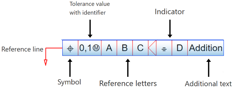
The geometric tolerances are indicated in a rectangular frame - the tolerance frame. It consists of one to five boxes, which can contain the symbol for the property to be tolerated, the tolerance value and the letter for reference elements etc. Furthermore, indicators and additional texts can be specified.
You can use the Form/Positional tolerances (3-D) function to insert tolerances with a reference symbol (DIN EN ISO 5459) as well as form/position symbols (DIN EN ISO 1101 and 14405-1). The dialogue window Form/Positional tolerances (3-D) is displayed for this purpose.
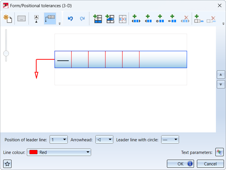
The content of the window differs for Reference symbols and Form-Position symbols
  .
.
|
Operating elements |
|
|
|
|
|---|---|---|---|---|
|
|
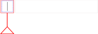
New form/positional tolerance empties the current content of the window and offers an empty sample of the tolerance |
|
|
|
|
|
Insert symbols opens or closes the toolbar |
|
|
|
|
|
Reference symbol switches to the Reference symbol mode |
|
|
|
|
|
Form-Position symbol |
|
|
|
|
|
Undo undoes the last input |
|
|
|
|
|
Redo restores the last undone input |
|
|
|
|
|
Attach new line |
|
|
|
|
|
Insert line at current position |
|
|
|
|
|
Delete current line |
|
|
|
|
|
Insert orientation plane indicator |
|
|

|
|
|
Insert cut plane indicator |
|
|
|
|
|
Insert collection level indicator |
|
|
|
|
|
Insert directional element indicator |
|
|
|
|
|
Remove selected indicator |
|
|
|
|
|
Append additional text |
|
|
|
|
|
Remove additional text |
|
|
|
|
|
Font settings With this function you define the text parameters for the tolerance specification. The parameters are font, colour and height as well as the line spacing. In addition, you can select the markup - bold or italic - for System Fonts or the aspect ratio and inclination for HiCAD fonts. If the aspect ratio is smaller than 1, the text will be compressed. Similarly, if the aspect ratio is greater than 1, the text will be stretched. With an inclination of 0.00 degrees, the text will be displayed normally. At an inclination of 15.00 degrees, the text will be displayed in italics. |
|
|
|
|
|
Favourites
|
|
|
|
|
|
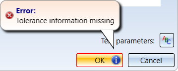
If the selected settings are incomplete or incorrect, this will be indicated by the OK button. If you point the cursor on the symbol, a corresponding message will be displayed.
|
|
|
|


The tolerance can be zoomed using the zoom slider  on the left of the window. In addition, you can scroll with
  and
and  for multi-line form/position symbols.
|
Reference symbol |
Form-Position symbol |
|---|---|
|
|
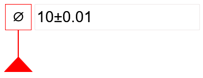
Reference symbol
To insert a reference symbol, activate the Reference symbol mode in the dialogue window. To clear the contents of the line, click  if necessary.
Then you can enter the tolerance values and letters. If you want to use identifiers, e.g. ![]() Maximum material condition or
Maximum material condition or ![]() Projected tolerance zone, or if you want to prefix the values in the input fields with the diameter symbol
Projected tolerance zone, or if you want to prefix the values in the input fields with the diameter symbol ![]() or the
or the ![]() symbol, activate the symbol selection by clicking on
symbol, activate the symbol selection by clicking on  .
.

Example:
Form-Position symbol
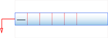
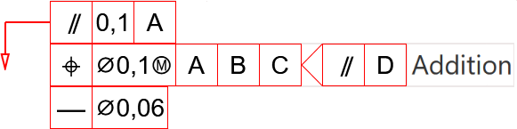
This symbol consists of one to five boxes. In addition, indicators and additional texts can be specified.
In the first box of a line, the property to be tolerated is specified. This can easily be selected from the drop-down list after clicking the box. The default setting is the Straightness property.
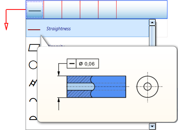
In the other boxes you can enter tolerance values, letters for reference elements, etc. and - analogously to the reference symbol - insert identifiers. Furthermore, indicators and additional texts can be added here.
Example:
To insert the tolerance - as shown in the dialogue window - click OK. HiCAD then prompts you to select a reference point. To do this, identify an edge or surface. The reference point is then determined by perpendicular from the cursor position to the edge/surface.
The symbol is then attached to the cursor and can be placed in the drawing by lowering the cursor (left mouse button). Instead of placing the cursor, you can also use the right mouse button to call the context menu shown below.
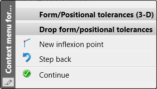
Here you have the possibility with the New inflexion point  function to insert inflexion points into the leader line. If you select this function, an inflexion point will be inserted at the corresponding position when you press the left mouse button. After that, the process of inserting the form/positional tolerance continues. This means that the next time you left-click, the symbol will be inserted, unless you insert further inflexion points.
After inserting a symbol, the Form/Positional tolerances (3-D) dialogue window is displayed again so that you can directly define and insert further symbols.

