3-D Grid
Drawing > Others > Extras  > 3-D Grid
Steel Engineering > Further functions > Settings > 3-D Grid 
Grids are an important construction aid for 3-D design. The 3-D Grid function can be used to define 3-D line grids. The grid lines are also called system axes in HiCAD.
The properties of a 3-D line grid:
- The grid line can have different distances in x- and y-direction. Different distances between 2 grid lines of one direction are also possible.
- The grid can be placed anywhere in the drawing.
- The intersection points of the grid lines are isolated points. You can access these points with the point option J.
- 3-D grids can contain of several layers (planes).
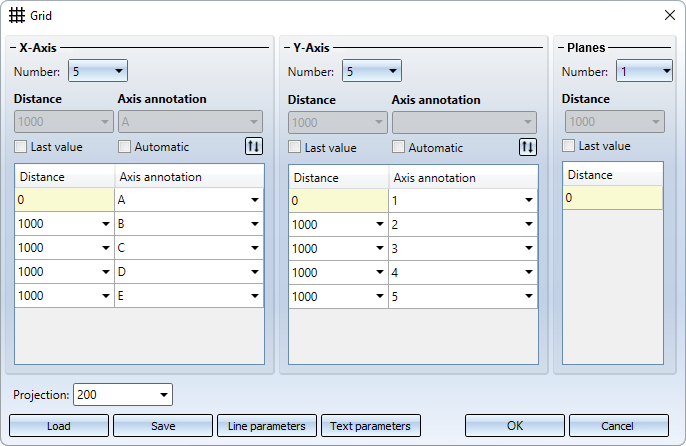
The Grid dialogue window is displayed to enable you to configure 3-D grids.
|
X-axis / Y-axis |
|
|---|---|
|
Number |
Number of grid lines in x-/y-direction |
|
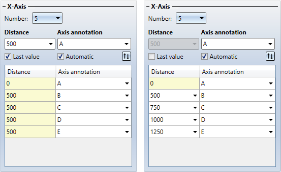
Distance |
For even axis distances, activate the Last value checkbox and enter the desired distance between the axes in the Distance field. If you want the distances between the axes to be uneven, deactivate the checkbox and enter the distances in the table.
When specifying the distance, you can also use formulas instead of values - even in mixed units. The value will then be converted to the unit of measurement of the drawing.
|
|
Axis annotation |
An axis annotation will always be created; if the Automatic checkbox has been activated, you can enter a start value for a consecutive axis annotation in the field above it. If you do not want the axis annotation to be consecutive, deactivate the checkbox and enter the axis annotation directly in the table.
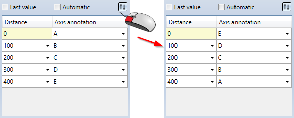
You can invert the axis annotation by clicking on the symbol
|
|
Planes |
3-D grids can consist of several planes. Specify the Number of planes and the Distance between each of the planes. Using multiple grid planes can be particularly useful in Steel Engineering, for example, if several beams located in the same plane need to be fitted. Examples include stages, bridge frames, substructures for car parks, roof constructions etc. When specifying the start and end points of the beams, you can then access the grid points directly, which speeds up fitting. |
|
Projection |
This value determines how far the grid lines will project beyond the border of the grid. |
|
Line parameters |
Click this button to specify the parameters for the grid lines. The Line parameters for 3-D grid dialogue window will be displayed, enabling you to select the colour, line type and layer of the grid lines. |
|
Text parameters |
Click this button to specify the text parameters for the axis annotation. The Text parameters dialogue will be displayed, enabling you to select the colour, layer size, font etc. of the axis annotations. |
|
Save |
Click this button to save the current grid settings. The data is saved in the HiCAD subdirectory Makro 3-D/Raster under the specified name with the extension .RST. The RST files can be reused at any time – even for other steel engineering constructions. |
|
Load |
Click this button to load a saved 3-D grid (.RST). |
 Result: 56.95 (mm)
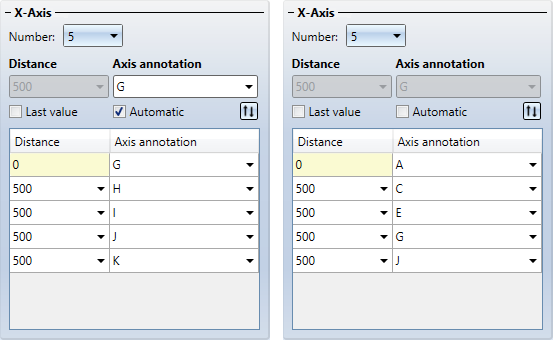
 .
.
If you have made the desired grid settings, choose OK to exit the window. HiCAD displays a preview of the grid.
To position the grid exactly:
- Choose a fitting point on the grid.
- Specify the position of this point in your drawing. If you want to place the grid in the origin of the coordinate system, press the right mouse button twice.
3-D grid with 2 planes
You can define so-called Grid sub-systems to refine the structure of 3-D grids or a Steel Engineering grids. Different sub-systems can be created on the various planes of the grid, and can also run diagonally to them. A grid sub-system consists of a start point and an end point and is represented as an edge. Along this refined grid, constructions can be erected, and the corresponding beams can be placed. You can find the function in the context menu for grids. You open the context menu by right-clicking the grid.
![]() Please note:
Please note:
- The grid is inserted into the 3-D part structure as a main part (Type = dummy part)
 called Grid. For each level of the grid, a sub-part named Grid (Type=part with free edges) is assigned to the main part.
 - The isolated points for the grid line intersections are only displayed and can only be identified if the representation of isolated points has been activated. To do this, activate the Isolated points checkbox under Drawing > Properties > Visualisation > Hide/Show, via element type
 .
. - A drawing can contain several grids.
- If you want to apply changes to a grid, e.g. if you want to move it, right-click the grid and select the appropriate function in the context menu. To change the grid settings, select the Change parameters function. Alternatively, you can delete and edit a grid using the feature log.
- The annotation of 3-D grid axes will not be shown in cut-outs, sectional views and detail views. In all other views the visibility depends on the viewing direction to the respective view, with a limiting angle of 5°. This means that if the direction vectors of the 3-D axes deviate less than 5° from the normal vector of the view (e.g. in front view or side view), the annotations for these axes will not be shown in this view, as they would otherwise intersect. As the visibility of the annotations must be set for each individual view, the annotations can only be assigned to the existing views. If new views are created, the annotations of existing grids will initially be hidden in these views. The information as to whether the annotations in this view should be shown will only be available after a recalculation of the grid. Therefore, annotations (if any) which were previously hidden can only be visualised after recalculation.
- On the Steel Engineering tab, select Further functions >
 Settings > Grid annotations to annotate the grid axes individually. In addition, you can apply the 3-D dimensioning functions to grids if desired.

