Move Sketch Elements
Sketch > Transform > Move 
Use this function to move lines and isolated points of a sketch. When you call the function, the Move dialogue window will be displayed:
![]()
The currently active step will be highlighted with an orange frame in the dialogue window. After calling of the function these steps consist in the selection of lines or points.
Step 1: Select option
Use the symbols at the top of the dialogue window to specify the handling of connected lines during moving.
|
|
Rotate lines, individually If this option is active, only the actually selected lines and isolated points will be moved. Connected lines will not be adjusted. |
|
|
Preserve connected lines and adjust length If this option is active, HiCAD will attempt to preserve the position of the connected lines if possible. In the process, the length of the lines to be moved may be adjusted by means of new intersections. For distances the angle between connected lines will be preserved. If it is not possible to preserve the connected lines, the
|


 symbol will be shown at the
Step 2: Select elements
Select the lines or isolated points that you wish to scale in the drawing, or use the functions of the context menu that you can open with a right-click during the selection process.

|
Connected lines or edges* Use this function to select all lines or edges that are connected to the next identified edge in one step. The lines and edges will be selected up to a point where a continuation would no longer be unambiguous. This function can also be activated with the help of the SHIFT key: If you select a line while holding down the SHIFT key, all connected lines will be automatically selected as well. |

|
Tangentially connected lines or edges* Choose this function if you also want to select all tangentially connected lines or edges when identifying the next line or edge. |

|
Lines and isolated points in rectangle (CTRL+LMB)* Use this function to select lines and points by means of a selection rectangle. Please note that only lines/edges and points of the active sketch will be considered. If the rectangle is drawn from the top left to the bottom right, all lines and isolated points which are completely located within the rectangle will be selected. If, on the other hand, the rectangle is drawn from the top right to the bottom left, lines/points that are only partially located within the rectangle (i.e. lines that intersect with the rectangle) will also be selected. The selected lines and isolated points will be highlighted in colour. You can also call the function via the keyboard. Proceed as follows:
|

|
Cancel (Esc) Cancels the function. |
*Normally, already selected elements (lines, edges and points) will be de-selected if you click them again. For the above functions marked with an asterisk *, however, the following applies: If you click elements that have already been selected or if already selected elements are located in a selection, they will not be removed from the selection.
The selected elements will be highlighted in the drawing and the number of selected elements will be shown in the dialogue window:
![]()
Press the middle mouse button to end the selection. Click the  icon to expand the selection.
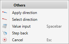
Step 3: Select distance / direction
After ending the line selection with the middle mouse button, HiCAD automatically switches to the displacement selection.
![]()
The following options are available for selecting the displacement:
- Determination of the reference point of the displacement,
- Selection of a straight line,
- Selection of a surface or
- Selection of the X-, Y- or Z-axis.
Determination of the reference point
Now determine the reference point of the displacement. This point and the selected sketch elements will then "hang" on the cursor. To select the new position of the line elements, you have multiple options:
- You move the selected line elements by determining the new position of the reference point. To do this, a distance grid will be displayed in the X and Y directions, as when drawing sketch elements.
or
- You activate the displayed context menu with further functions by right-clicking.
|
Funktionen |
|||||||||||||
|---|---|---|---|---|---|---|---|---|---|---|---|---|---|
|
|
The connection between the selected reference point and the current cursor position is taken as the direction of the displacement. |
||||||||||||
|
|
This function allows you to select the direction for the displacement. To do this, you define the direction vector by determining two points, by selecting a straight line or by selecting a surface. If a surface is selected, the direction will be determined by the surface normal. In addition, you have the option of using the right mouse button to activate a context menu with further options for determining the direction.
|
||||||||||||
|
|
Select this function to explicitly specify the distance - either the length of the direction vector or the X and Y distance to the selected reference point. HiCAD displays the calculator for this purpose. Instead of calling the function, you can also simply press the space bar. The X and Y distance can also be entered directly together if you separate the two values with a space. |
||||||||||||

|
Step back If you want to jump back one or more steps to correct the input, select the function Step back (multiple times, if necessary). |
||||||||||||
|
|
Cancel (Esc) The function is cancelled. |
||||||||||||


When selecting a straight line, the direction of the displacement is determined by the cursor position and visualised in the drawing. The length of the selected line is displayed as distance in the calulator.
When selecting a surface, the direction of the displacement is determined by the surface normal and the current cursor position and visualised in the drawing. The distance displayed in the calculator is 1.
Selection of the X-, Y- or Z-axis
If you right-click during the 1st point, straight line or surface for direction prompt, a context menu for selecting the axis will be displayed.
![]()
You can then select an axis of the active coordinate system to determine the direction.
To change the direction, click the  icon and specify the new direction.
If you want to move the selected lines/points - as shown in the preview - click OK.
Example:
As an example, let us consider the following sketch.
![]()
![]()
A: Move lines individually, B: Preserve connected lines and adjust length(1) Selected lines ; (2) Selected direction, (3) Result
![]() Please note:
Please note:
- Instead of clicking Apply in the dialogue window, you can also press the middle mouse button (MMB) to apply the displacement.
- A displacement is only possible within the sketch plane.
- The selected lines and isolated points must belong to the same sketch. Otherwise, a corresponding error message will be displayed.
- HCM constraints will be adjusted if possible. If an adjustment is not possible, they will be removed.
- Undo is possible when the dialogue window is open.
- In certain geometrical situations, using the Preserve connected lines and adjust length option may produce "odd" results.
An example:
In case A the selected line (1) is moved in the direction (2). The result is an apex (3) with a degenerated straight line. If you delete the 3 normal lines, the degenerated straight line will remain permanently in the drawing.
![]()
In case B the selected line (1) is moved in the direction (2), resulting in multiple coincident straight lines. These can be trimmed in hindsight, which is, however, not immediately apparent.
- You can also use the Move points function to move sketch elements.

