Point Grid
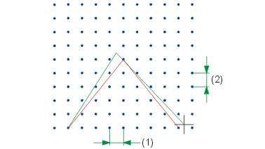
If the grid is activated, all points that you generate with the RETURN point option are referred to grid points. If a point grid is active, you can move the cursor as required, even between the grid points. When specifying the points in polyline mode, for example, you position the cursor on the individual grid points.
There are various ways of making the point grid visible on the screen. Open the Configuration Editor (ISDConfigEditor.exe) and select System settings > Identification > Representation of identification grid. The following settings are possible:
- If you only want a rough outline of the point grid to be displayed, set the parameter to -1.
- If the parameter is set to 0, a circular signature is drawn for every grid point displayed.
- The grid can be displayed on the graphics screen in the form of grid lines that are orthogonal to one another. For this, the corresponding parameter must have a value between 1 and 9. This value is used at the same time as a line type for the grid lines. This type of representation is used if you want the grid to act as a construction aid.
Point grid On
2-D Geometry > CAids > Grid  > Point grid ON
 ![]()
You use this function to define and activate a point grid. All points the coordinates of which are obtained by converting the cursor position are rounded to the nearest grid point if the grid is activated. Specify the distance in x- and y-direction for the point grid. The default setting in HiCAD is 10 mm.

Point grid Off
2-D Geometry > CAids > Grid  > Point grid OFF
 ![]()
You use this function to deactivate a point grid you have defined. All points are displayed, according to the point options used.

