Railing Configurator - Railings along Edges
'Civil Engineering functions' docking window > Steel Engineering >Stairs + Railings > Railing > Railing Configurator (Railings along edges)
The Railing Configurator enables you to create individual railings along edges - for example, railings on balcony platforms (solid) or concrete stairs.
You can select edges of solids (body edges), of sketches or of 3-D sketches (part with free edges), or a combination of these edge types.
Important:
- The drawing must contain a main assembly. If this is not the case, a corresponding message will be displayed. Extensive information on main assemblies can be found in the topics Assemblies, Main Parts and Sub-Parts, Part Drawing or Assembly Drawing and Edit Part/Assembly Structure. If no main assembly exists, the following message will be displayed.
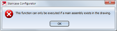
Select Yes if you want to create a new main assembly. In this way, railings along edges can be directly inserted.
- The edges along which the railing is to be placed must form one continuous "path", i.e. two successive edges must have an intersection point. Two successive edges must not run parallel to each other. The path of the edges must not form a loop.
- The Z-axis of the active coordinate system is the direction axis for the posts, which means that the beams must not run parallel to the Z-axis of the active coordinate system.
- The edges must be straight.
When you start the Railing Configurator, HiCAD will prompt you to identify, one after the other, the edges along which the railing is to be placed. The "path" that is defined by these beams is the "virtual guideline" determining the route of the railing. Posts, handrail, infill and knee rail of the railing will be located on c-edges running parallel to this guideline (the so-called "walking line"). When selecting the edges, please note that the first selected edge will for HiCAD be the start to which the later subdivision of the railing will refer (Fixed distance, with Patch at start or Patch at end).
The walking line and the walking direction are indicated by a red arrow. The height of the railing and also the fixing position refer to this walking line. The distribution of posts, too, will be visualized on the basis of the last selected settings. As soon as you change the settings in the Railing Configurator dialogue window, the preview will be updated.
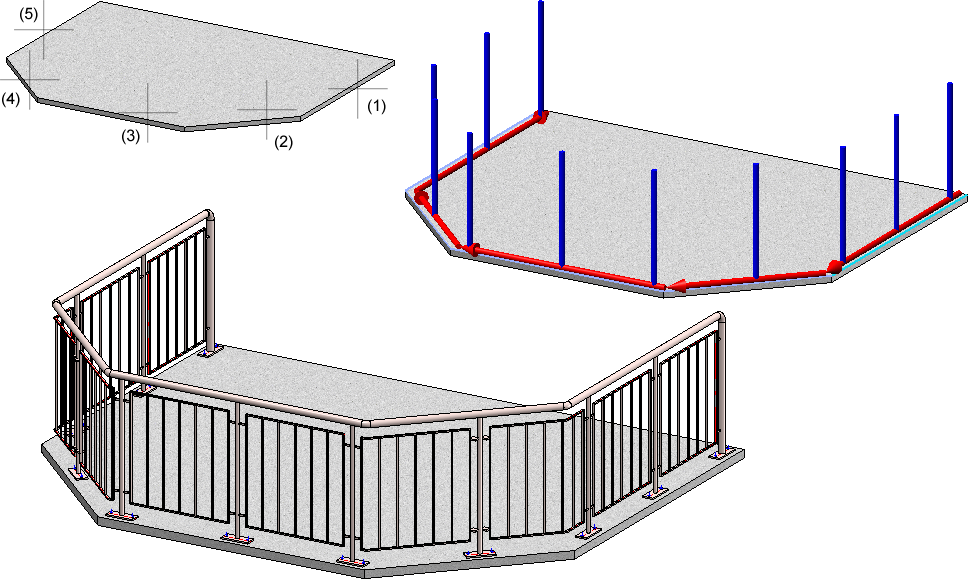
Top: Solid with selected edges; Bottom: Example of a railing
Press the middle mouse button to end identification of beams, which automatically opens the Railing Configurator dialogue window. The operation of the dialogue window is largely identical to that of the Railing Configurator (along beams) function, the only difference being the explanatory graphics in the Walking line and the Post distribution tab.
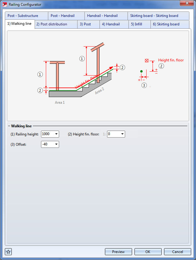
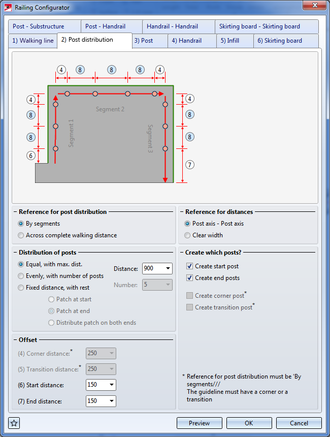
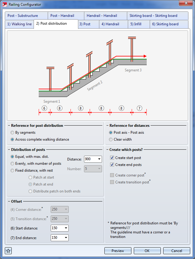
The dialogue window is identical to that of the Railing Configurator - along beams function, with the exception that the options and input fields for beam processing are not relevant here.
Click OK to start the generation of the railing. The status of the railing generation will be indicated by a progress bar. HiCAD creates a corresponding feature entry, Railing along edges.
HiCAD will create an assembly called Railing. This assembly is subdivided into further assemblies called Segment, which contain the railing elements of the individual beams.
The settings can be saved as Favourites and reused at any time. At the bottom left of the dialogue window, click the  symbol to activate a menu with Favourites functions. More information about Favourites can be found in the Manage Favourites topic of the HiCAD Basics Help.
While the window is open, you can display a Preview of the railing generated with the current settings by clicking the same-named button. You can use the zoom functions to enlarge or downsize the object on the screen.
Click OK to start the generation of the railing. The progress of the generation will be indicated in a progress bar.
 Please note:
- It is also possible to create customer-specific Design Variants for the components. If you require further information, please contact our Consulting department.
- All settings made in the Railing Configurator dialogue window will be the new default settings when the configurator is called again.
- Please also read the information given in the topic Railing Configurator - Important Notes (3-D SE).
- For concrete stairs, it makes sense to use only one lateral anchor for each post.
- You can also create curved railings in one plane, i.e. the composite edge may also contain arcs.
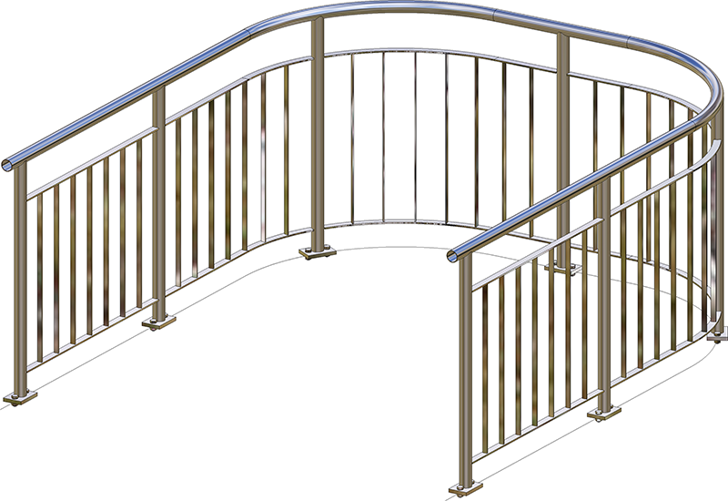
Curved railing, created on the basis of arcs
Please note:
Even if you activate the All posts equal checkbox on the Post tab, the settings on the tabs Post - Substructure and Post - Handrail will not be considered for corner posts and transition posts! The connections on corner posts and transition posts must therefore be reworked manually.


Railing Configurator - Railings along Beams (3-D SE) • Steel Engineering Functions