Process Beams
The Steel Engineering tab provides the following beam processing functions:
|
Trimming beams to edges, surfaces and parts |
|
|
Changing the length of beams |
|
|
Notching with or without lengthening |
|
|
More processing functions like exchanging and adding of beams, changing the representation, curving and moving of beams. |
In addition, you can use the 3-D functions for the processing of beams. They enable you, for example, to transform and shape parts.
![]() Please note:
Please note:
- Most functions provide various function variants
- Some processing functions can be applied simultaneously to several beams, i.e. a bill of materials.
- If you want to process series beams, please make sure that the assembly is active. You can also choose the Group snap identification mode. In this case, if you select a part belonging to an assembly, the assembly is directly activated.
- If you process beams to which an item number has already been assigned, the item number will be marked with an asterisk * or is displayed as a strikethrough number (depending on the chosen setting for ICN display) after processing. In this case, you should re-itemise the relevant beams before creating workshop drawings, bills of materials etc. Please note the following:
- If you do not want this modified display of the item number, open the Configuration Editor, choose System settings > Itemisation > Updating and deactivate the Set change mark when changing parts checkbox.
- When changing part attributes, the modified display is only assigned if the attribute is taken into account for identical part search.
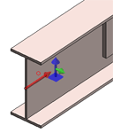
- If the active part of the drawing is a Steel Engineering beam or profile, its orientation, i.e. the
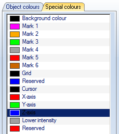
- axis direction (in the Special colour X-axis)
- top/bottom (in the Special colour Z-axis),
- left/right (in the Special colour Y-axis)
can be indicated by means of a corresponding symbol in the active view.

The indication of orientation can be set in the Configuration Editor , at ... > System settings > Visualisation > Indicate orientation of active Steel Engineering beam. The following options are available:
- Only upon insertion
The orientation of the beams will only be indicated when they are inserted. This is the default setting. - Always
The orientation will always be indicated (if set). - Switch on/off with F6 key
The indication of the orientation can be switched on or off with the F6 key. Alternatively, you can also use the
 Show beam orientation or drawing alignment of the active 3-D part [on/off] symbol on the Coordinate systems toolbar (at the bottom of the dialogue window) for this.
The colours of the orientation symbol can be changed via the Colour Editor  (Drawing > Others > Colour Editor).


