"Civil Engineering functions" docking window > Steel Engineering > Connections > Individual beam/profile > Base plate + Anchor plate (2101) 
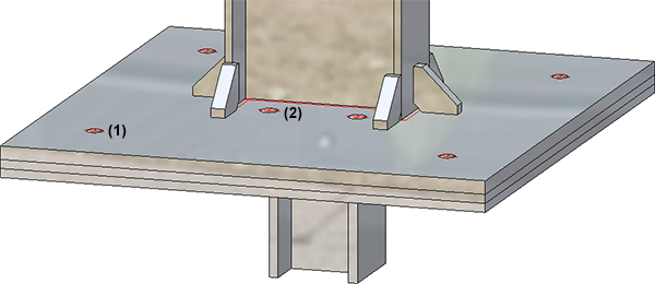
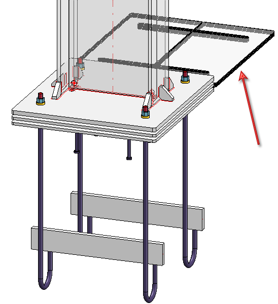
Use this function to insert base plates and anchor plates for columns (vertical beams). Insertion can take place with welded plates and anchor plates complete with shear connectors (with a front plate if desired) and head studs or anchors with inserts. The insertion of ribs as additional stiffening elements on flanges and webs, or the applying of galvanization holes are also possible.
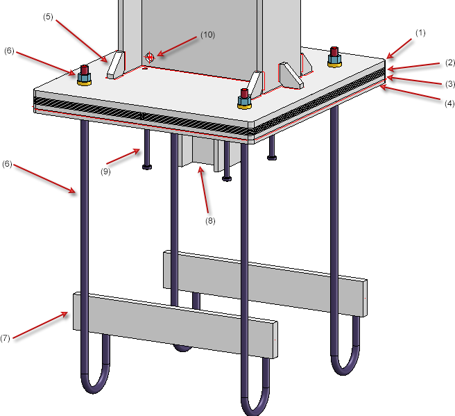
(1) Base plate, (2) Filler plates, (3) Welded plate, (4) Anchor plate, (5) Ribs, (6) Bolting )base plate) , (7) Insert, (8) Shear connector with front plate, (9) Head studs, (10) Galvanization holes
Proceed as follows:
Identify the beam. Allowed beam and profile types are I-beams, U-beams, L-beams, T-beams, Z-profiles, as well as square steels, round steels, hollow profiles and steel pipes.
Click the Preview button if you want to display a preview of the connection based on the currently entered data. If you want to modify the current data, apply the required changes and click Preview again to update the preview. Click OK to insert the connection according to the current data and close the dialogue window. If you click the Cancel button, the window will be closed, and the specified or changed connection will not be inserted.
Symbols:
|
|
Selected parts Click on this symbol to show information on the previously identified beams, such as the type of the beam, the material, the dimensions, etc. Value inputs and changes are not possible here.
|
|
|
Invert concerned connection values horizontally Click on this symbol to switch specified values horizontally, i.e. right and left. For instance, this can be done for
|
|
|
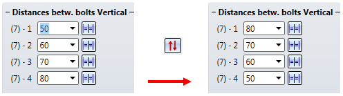
Invert concerned connection values vertically Click on this symbol to switch specified values vertically, i.e. top and bottom. For instance, this can be done for
|
|
|
The settings in the dialogue window can be saved as Favourites and reused at any time. To do this, click on the |


Notes on assembly structures:
When you insert the Base plate + Anchor plate connection, the following assemblies will be created (depending on the current configuration) as a result:
- The base plate and the ribs will be assigned to the assembly of the selected beam (the column). The assembly main part is the beam.
- Filler plates and inserts will be assigned to the structure assembly Loose part. This assembly is located on the same structure level as the column assembly.
- If you have selected the assignment option Loose part for bolting insertion, the bolting will be placed in an assembly called Bolting and will also be assigned to the structure assembly Loose Part, or otherwise to the assembly of the column.
- The Anchor plate assembly contains the shear connector as assembly main part, the front plate, the head studs and the anchor plate. The head studs are placed into a non-BOM-relevant assembly called Standard part group. If you have chosen the insertion of threaded studs instead of the bolting, these will also be assigned to this assembly, with studs, welded studs, nuts and washers each being placed into one assembly called "Standard part group".
- Weld seams always assigned to the assembly to which the corresponding plate, rib or stud belongs, e.g.
- Beam - Base plate
 Assembly of beam
 - Beam - Ribs Assembly of beam
- Ribs - Base plate Assembly of beam
- Anchor plate - Welded plate Assembly of anchor plate
- Anchor plate- Shear connector Assembly of anchor plate
- Head stud - Anchor plate Assembly of anchor plate
- The welded plate will be inserted as an individual part.
 Please also note:
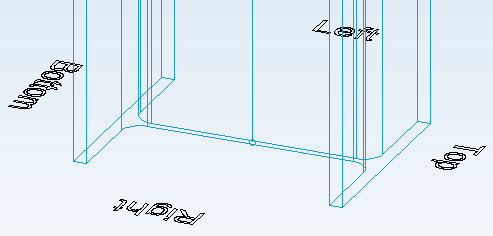
- HiCAD will indicate the top/bottom/right/left positions in the drawing during input of the required data. The texts will be aligned in Z-direction.
- The components of the base plates and anchor plates will be loaded from the HiCAD Standard part catalogues. If you wish to use your own beams, profiles, plates, bolts etc. you need to expand the corresponding tables in the Catalogue Editor accordingly.

Configure base/anchor plate
The base plate/anchor plate connection is defined by the settings on the following tabs of the dialogue window:
- Plates,
- Fixing,
- Bore grid,
- Galvanization,
- Weld seams,
- Filler plate,
- Shear connector,
- Head studs and
- Ribs.
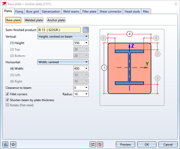
Here you specify type and size of the base plate, weld-on plate and anchor plate and their alignment in relation to the selected beam.
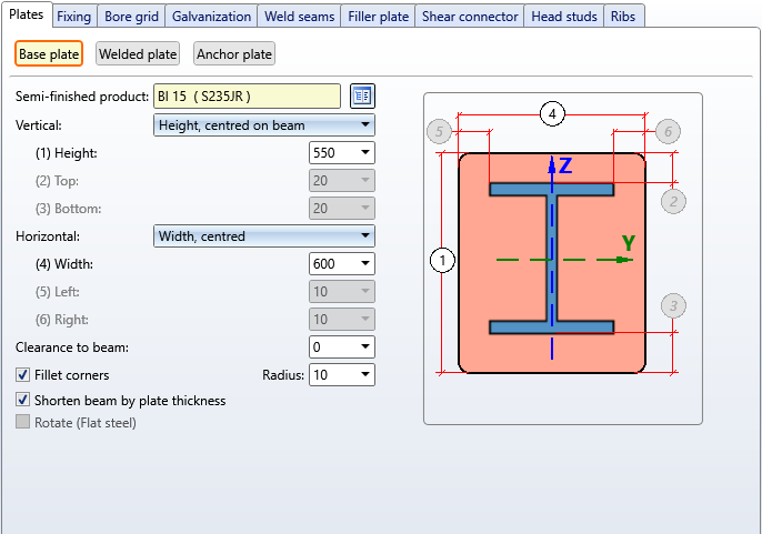
The settings for the different plates takes place on the sub-tabs on the left side of the window. Anchor plates and welded plates are only inserted if you have activated the Create checkbox on the corresponding sub-tab.
|
Create |
Anchor plates and welded plates are only inserted if you have activated this checkbox on the corresponding sub-tab. |
|
Congruent (Base plate) |
If you want the anchor plate or welded plate to be congruent with the base plate, activate this checkbox. no value inputs in the Vertical/Horizontal fields will then be required. |
|
Semi-finished product |
Click the |
|
Vertical |
|
|
Horizontal |
|
|
Clearance |
If desired, enter a value for the clearance here, i.e.
|
|
Fillet corners |
If you want the corners of the plate to be filleted, activate this checkbox and enter a fillet radius. |
|
Shorten beam by plate thickness |
Activate this checkbox if you want to shorten the beam by the thickness of the plate that is to be mounted onto the beam. The thickness of pre-planned filler plates and the clearance of the base plate (distance to beam) will be taken into account in the process.
|
|
Rotate (Flat steel) |
Various semi-finished product types, e.g. flat steel, offer the option to rotate the plate before insertion: To do this, activate the checkbox. |
Here you specify whether the fixing is to be done by means of boltings or threaded studs.
To do this, activate the corresponding Fit checkbox. The relevant input fields will then be active.
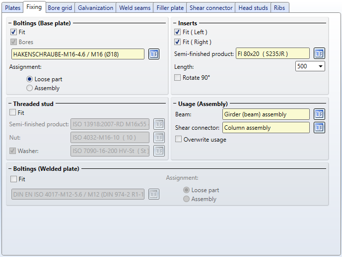
Boltings (Base plate)
If the fixing is to be made by a bolting into the anchor plate from the bottom, then activate the Fit checkbox. Base plate, welded plate and anchor plate are then bolted together. Determine the components of the bolted connection by clicking on the  symbol. The determination is done analogous to the function New bolting/riveting. Base plate, welded plate and anchor plate are then bolted together. Instead of the complete bolting, only the bores can be installed, i.e. the plates are only pre-drilled.
Under Assignment you determine to which assembly the boltings are to be assigned. If the option Looose part is active, the boltings are combined in a separate assembly with the name Bolting. If the option Assembly is selected, the assembly Bolting is assigned to the assembly of the selected beam.
Alternatively, fastening can be done by threaded studs or by a screw connection countersunk into the weld-on plate from ther bottom.
Threaded stud
If the fixing is to be done by threaded studs, activate the checkbox Fit here. Then select the desired welded stud as well as nut and washer under semi-finished products. The base plate and welded plate are then connected by the threaded stud. The different standard parts are each combined in an assembly called Standard part group and assigned to the assembly with the anchor plate.
Boltings (Welded plate)
If the checkbox Fit is activated, the fixing is done by a screw connection countersunk into the welded plate from the bottom, i.e. only welded plate and base plate are bolted together. Determine the components of the bolted connection by clicking on the symbol. The determination is analogous to the function New bolting/riveting. Base plate and welded plate are then bolted together.
Under Assignment you determine to which assembly the boltings are to be assigned. If the option Loose part is active, the boltings are combined in a separate assembly with the name Bolting. If the option Assembly is selected, the assembly Bolting is assigned to the assembly of the selected beam.
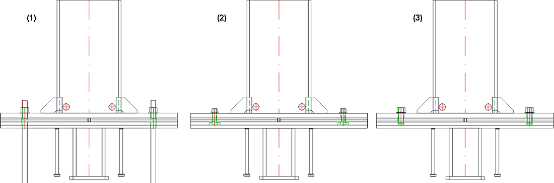
Fixing: (1) Bolting (Base plate), (2) Bolting (Welded plate), (3) Threaded stud
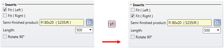
Inserts
If the checkbox Fit is activated under Boltings (Base plate), then the area Inserts is also activated. If you want to insert inserts, activate the checkbox Fit. To select the insert, click on the symbol and select the part in the catalogue. Then determine the length. By activating the Rotate 90° checkbox, the part can be rotated during insertion.
Usage (Assembly)
Here you can specify the usage of the selected beam and the shear connector. If a usage has already been assigned to the assembly of the beam, the Overwrite usage checkbox can be used to specify whether the existing usage is to be kept or replaced by the usage type selected on the Fixing tab.
Please note that the usage can only be set before the creation of the assembly structure. As soon as you click the Preview button or the OK button, a change is no longer possible.
The tab is divided into two sections:
- Bolting
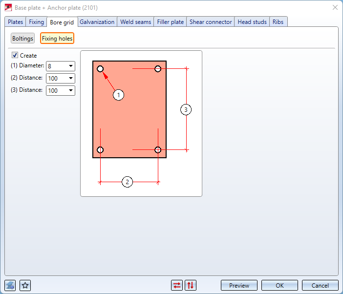
Here the arrangement of the bolting, the hole pattern or the threaded studs on the plate is defined. - Fixing holes
Here you determine whether additional fixing holes are to be created that are independent of the bolting. In practice, these are sometimes needed, for example, to temporarily fix the base plate with nails when mounting the column. In this case, determine the diameter of these holes and their horizontal and vertical distance from each other.
(1) Bores for the boltings, (2) Fixiing holes
.
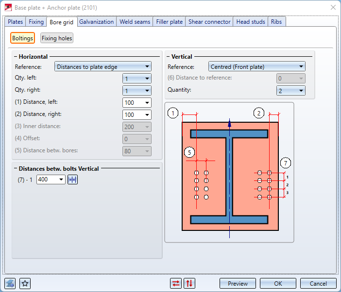
Boltings
For both the horizontal and the vertical settings you need to select a reference first. Further inputs are then dependent on the selected reference.
|
Horizontal - Reference |
Inputs |
|
Distances to plate edge |
|
|
Inner distance
|
|
|
Distances to web |
|
|
Vertical - Reference |
Inputs |
|
Centred (Front plate) |
|
|
Ref. beam, upper edge |
|
|
Front plate, top |
|
|
Ref. beam, lower edge |
|
|
Front plate, bottom |
|
You can use different vertical distances between bores. If you want all vertical distances between bores to be equal, the easiest way to achieve this is to enter the desired distance value in one input field and click the Equidistant  icon. All input field will then be filled with the same value.
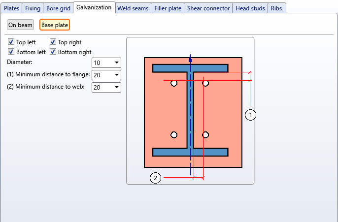
Here you specify whether you want to apply holes for galvanization processes to the base plate and the reference beam. Activate the corresponding sub-tabs on the left hand side for this purpose.
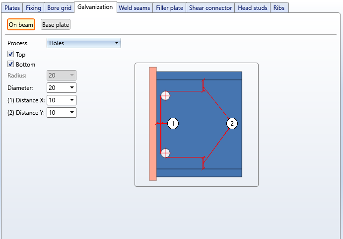
On beam
Here you select the desired processing. Possible are the following settings:
- - (no processing)
- Web cut
Choose whether the processing is to be applied at the top or bottom and enter a radius. - Holes
Choose whether the processing is to be applied at the top or bottom. Enter a hole diameter and the distance to the web (Distance X) and to the flange (Distance Y).
Base plate
Use the checkboxes to specify which bores are to be created. Enter a hole diameter and the minimum distance to web and flange.
(1) Processings on beam: Holes, holes in plate, (2) Processings on beam: Web cut at top/bottom, holes in plate
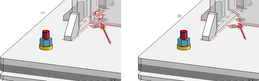
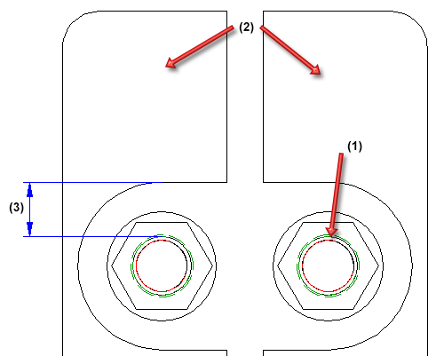
In the workshop drawings, only one of the zinc plating holes for galvanisation is annotated. Please note however that this principle only applies to zinc plating holes on beams.
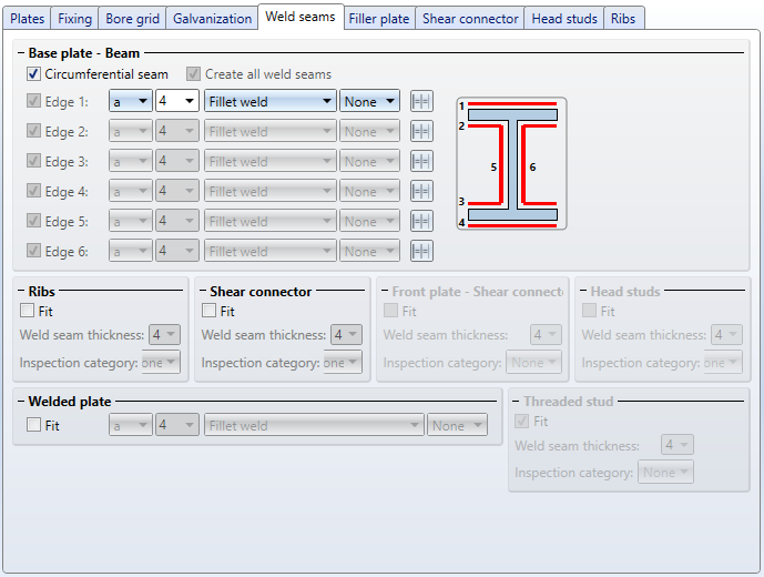
Here you specify, by activating or deactivating the checkboxes, which weld seams are to be created between beam and base plate. The following options are possible:
- a circumferential seam,
- weld seams on particular edges, or
- all weld seams.
For each edge you can select a type of thickness designation, the weld seam thickness, the weld seam type and the inspection category. If you want to use the same settings for the other edges, click the Equate icon.
In addition, you can specify here whether weld seams are to be inserted
- on the ribs (between beam and ribs, and between ribs and base plate),
- between anchor plate and welded plate,
- between anchor plate and shear connector,
- between anchor plate and head studs
- between anchor plate and threaded studs, and
- between front plate and shear connector
To do this, activate the Fit checkbox and enter the weld seam thickness. In the listbox for the Inspection category you can select the test/inspection method according to DIN EN 1090. These inspection categories are predefined in the Configuration Editor at Modelling > Weld seams. They will be evaluated during creation of Weld Seam Test Protocols.
For the welded plate you can select a weld seam type from a listbox.
For continuous HV and HY weld seams, enter 0 as the weld seam thickness.
If you want filler plates to be fitted between base plate and welded plate, you can specify the number of plates, the type and the size of these plates here.
The following geometry types are available:
- One-piece, insert left,
- One-piece, insert right,
- One-piece, insert top,
- One-piece, insert bottom,
- One-piece, drilled,
- Two-piece, insert horizontal and
- Two-piece, insert vertical.
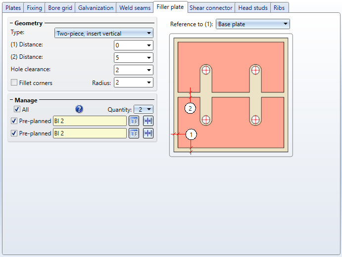
Depending on the selected geometry type, enter the distance to the plate edge and the distance between the filler plates. The distance to the plate edge can refer to either the base plate or the welded plate. Select the desired plate in the list box Reference to (1). The size of the filler plates is determined by the distance and the reference.
Determine the size of the hole clearance. The hole clearance always refers to the screw.
(1) Bolt diameter, (2) Two-piece filler plate, (3) Hole clearance
Beneath Manage you can specify the number of the filler plates.
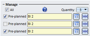
For each filler plate, select the desired sheet type from the catalogue  and specify, by activating or deactivating the corresponding checkbox, whether the filler plate is to be pre-planned or not. If the filler plate has been defined as "pre-planned", the beam will be shortened by the thickness of the filler plate. Non-pre-planned filler plates will be created beside the beam.
Use the icon to apply the settings on one filler plate to all other filler plates.
By activating the All checkbox, all filler plates can be defined as Pre-planned.
Please note that non-pre-planned will be displayed as transparent parts in the drawing, i.e. they will be assigned to Layer 40.
Non-pre-planned filer plates
Filler plates are not assigned to the assembly of the beam, but will be placed in a separate structure assembly called Loose parts. They obtain the usage Filler plates.
 If the bore grid is too narrow, preventing the fitting of filler plates, the plate will not be created. However, a feature log entry will be created.
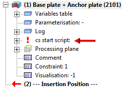
Double-click the name of the feature to change the settings.
Here you determine the profile for the shear connector, its length and its material. Click the icon to select the profile and the material directly from the corresponding standard part cataogues.
Beneath Positioning you can specify an offset of the shear connector in relation from the plate.
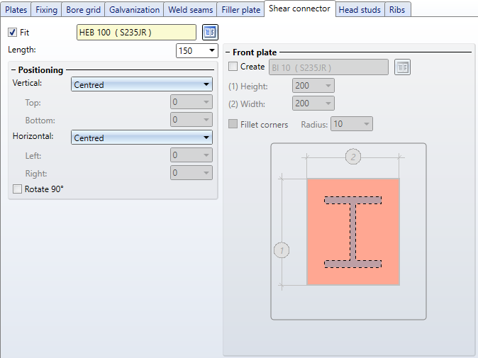
If you want to attach a front plate to the shear connector, activate the Create checkbox under Front plate. If desired, the front plate corners can also be filleted by activating the corresponding checkbox.
Here you specify whether head studs are to be fitted. If so, activate the Fit checkbox and select the desired bolt.
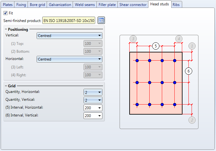
Beneath Positioning you determine how the head studs set is to be aligned horizontally or vertically on the plate.
Here you have the option to attach additional stiffeners - so-called ribs - to flange or web.
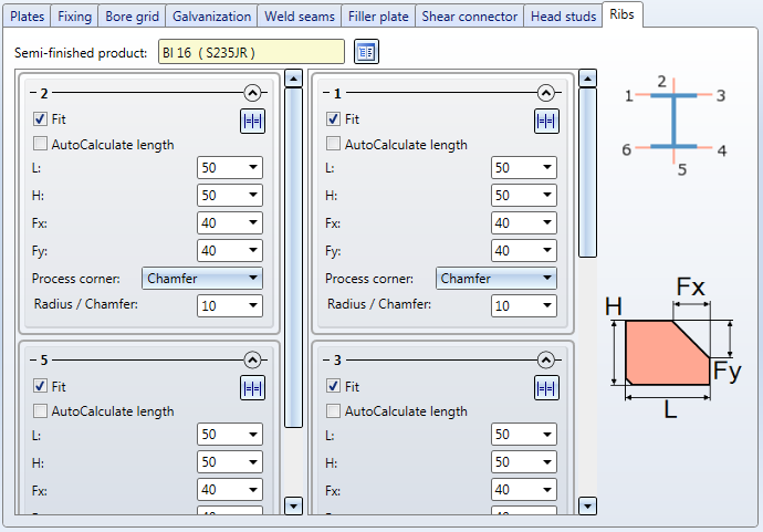
For each of the possible stiffeners (2 and 5 to web, 1, 3, 4, and 6 to flange), the following parameter settings are possible:
Fit
By activating or deactivating this checkbox you specify whether the corresponding stiffener will be inserted or not.
AutoCalculate length
If this checkbox has been activated, the length of the stiffeners will be automatically calculated. If you do not want this, deactivate the checkbox and enter the length yourself.
Height, Chamfer X, Chamfer Y
Here you specify the height of the stiffener and the chamfer length in X- and Y-direction.
Process corner
Here you define the processing of the inner corner of the of the stiffener. Possible settings are:
- None
- Chamfer
- Inner fillet
- Outer fillet
Depending on the selected option, enter either the chamfer length or the fillet radius.
Click the icon to apply the settings specified in the current input area to all other stiffeners in this direction. For instance, if you process area 1, i.e. in flange direction, and then click on the icon, the settings in the areas 3, 4 and 6 will be adjusted automatically.

Connections + Variants (3-D SE) • Dialogue Window for Connections (3-D SE) • The Catalogue System for Connections + Variants (3-D SE)