Free Plate (1103)
"Civil Engineering functions" docking window > Steel Engineering > Connections > Individual beam/profile > Free plate (1103)
Use this function to insert plates of flat steel or sheet metal with pre-drilled holes. Besides standard bores, slots and free bores can be used if desired.
When you call the function, the dialogue window for free plates will be displayed.
The settings in the dialogue window can be saved as Favourites and reused at any time. To do this, click on the  at the bottom left of the window to activate the context menu. More about Favourites management can be found in the Manage Favourites topics of the HiCAD Basics Help.
![]() Please note:
Please note:
If the part that is active when you call the function is already a sub-part to an assembly, the plate will be inserted as a sub-part to this assembly. Otherwise, the plate will be inserted as a main part in the drawing.
If the Insert as attached part checkbox is active, HiCAD will proceed as follows with regard to the part structure:
- If the active part already belongs to a BOM-relevant assembly, the plate will be assigned as a sub-part to this assembly.
- If the active part does not belong to a BOM-relevant assembly, a new BOM-relevant assembly will be created, to which the active part and the and the plate will be subordinated.

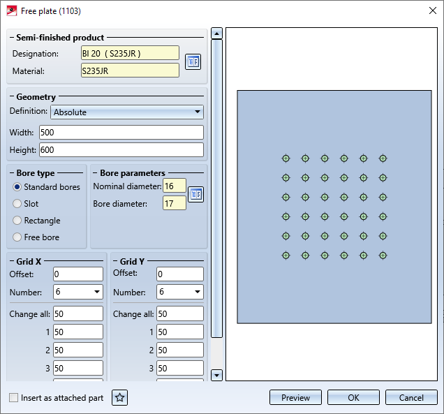
Configure free plate
Semi-finished product
The plate can either consist of flat steel or of sheet metal. Click the  icon to select plate type and material directly from the corresponding Standard part catalogues.
Geometry
Here you can determine the plate size. In the Definition listbox you can choose between the following procedures:
- Definition: Absolute
The plate size is determined by specifying the height and width of the plate. - Definition: With projection from grid
The plate size is determined by the identified beam and the specified projection from the bore grid.
(1) top, (2) bottom, (3) left, (4) right
Bore type
The following options are available:
- Standard bores
Click on the icon and select the desired bore directly from the Standard Part catalogue. - Slot
The bore has the form of a slot. Specify the length and diameter of the slot. If you want to rotate the slot, specify the rotation angle.
Slot (left) and Rectangular slot (right)
- Rectangle
The bore has the form of a rectangular slot. Specify the length and width of the slot. If you want to rotate the slot, specify the rotation angle. - Free bore
Select this bore type if you want to use a simple bore defined by diameter specification.
Grid X/Y
The bore grid determines the arrangement of the bores on the plate.
- X- and Y-offset (distance to the centroid of the plate)
- Number of bores in X- and Y-direction and their distance to each other. If you want all bores running in one direction to have the same distance to each other, you can simplify the data entry by doing the following: Just enter the distance value into the field Change all.
Insert as attached part
If the part that is active when you call the function is already a sub-part to an assembly, the plate will be inserted as a sub-part to this assembly. Otherwise, the plate will be inserted as a main part in the drawing.
If the Insert as attached part checkbox is active, HiCAD will proceed as follows with regard to the part structure:
- If the active part already belongs to a BOM-relevant assembly, the plate will be assigned as a sub-part to this assembly.
- If the active part does not belong to a BOM-relevant assembly, a new BOM-relevant assembly will be created, to which the active part and the and the plate will be subordinated.
Click the Preview button if you want to display a preview of the connection based on the currently entered data. If you want to modify the current data, apply the required changes and click Preview again to update the preview. Click OK to insert the connection according to the current data and close the dialogue window. If you click the Cancel button, the window will be closed, and the specified or changed connection will not be inserted.
HiCAD displays a graphical preview for the insertion of the plate. Specify a fitting point in the graphic, then specify the position of this point in the current drawing.

Connections + Variants (3-D SE) • The Dialogue Window for Connections (3-D SE) • The Catalogue System for Connections + Variants (3-D SE)