HiCAD Point Clouds - What's New?

Service Pack 2 2022 (V 2702)
Plane from points - orthogonal to a plane, parallel to a direction
The only reliable criterion when processing point clouds is the Z direction of the world coordinate system. Therefore, in most cases, a processing plane is required when constructing a point cloud, which fits the object as well as possible, but does not have an angle - even if the point cloud itself has an angle, e.g. due to inaccuracies.
To create such processing planes, the function Plane from points  has been extended. In the Parallel and Orthogonal mode, you can now select either a plane or a direction. The dialogue window has been extended accordingly:
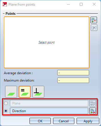
With this extended window, planes for the following use cases can now be realized as follows:
- Mode: Parallel, Plane: XZ-plane or
- Mode: Orthogonal, Plane: Z-axis
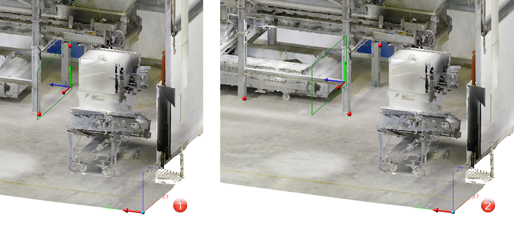
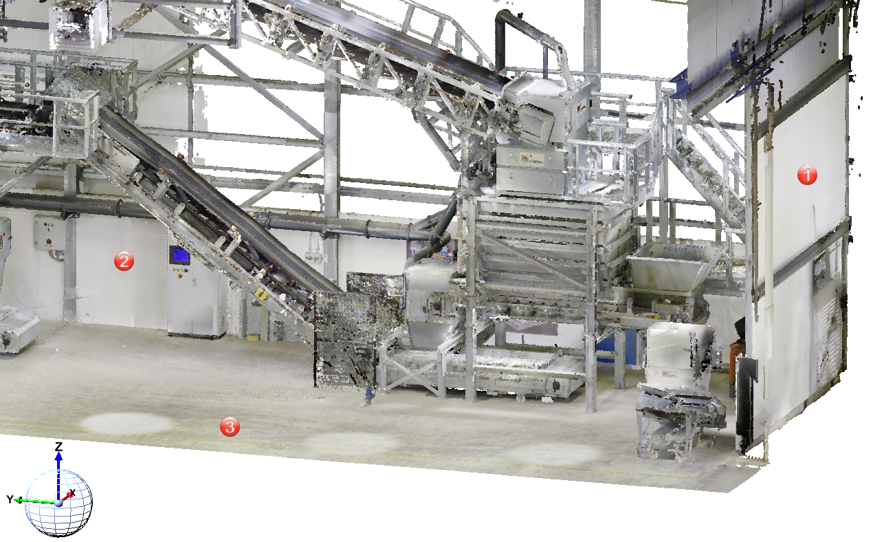
Example:
Let us assume that you want to attach further elements at the points (1), (2), and (3). The World CS is active.
Then you will select the processing planes as follows:
(1) Mode: Parallel, Plane: XZ-plane
(2) Mode: Parallel, Direction: Z-axis
(3) Mode: Orthogonal, Direction: Z-axis
Service Pack 1 2022 (V 2701)
No Point Cloud license
If no licence for the Point Cloud module is active when opening a drawing file with point clouds, the following message appears:
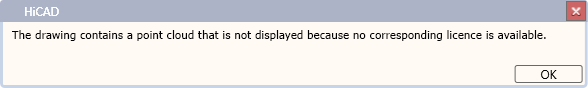
The message disappears automatically after a few seconds, but can also be terminated with OK.
Major Release 2022 (V 2700)
Clipping
With the release of HiCAD 2022, working with clipping boxes has changed, which is also reflected in the changed Point Cloud Ribbon:
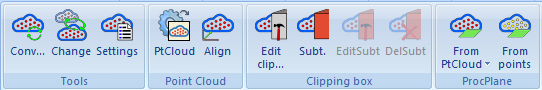
The new and changed functions:
|
|
Edit clipping box When inserting a point cloud, a clipping box is automatically created that completely encloses the point cloud. This box can be scaled, moved and rotated using the Edit clipping box function. The box cannot be deleted and no further clipping boxes can be created. The old "Create clipping box" function is no longer available. |
|
|
Subtract This new function can be used to create one or more subtractions in the clipping box and thus temporarily "cut away" areas of the point cloud. |
|
|
Edit subtractions This function allows you to move, rotate and scale subtractions. |
|
|
Delete subtractions This function deletes subtractions. |


The possibility of working with subtractions has made the old "Toggle clipping box" function obsolete. It is therefore no longer available.
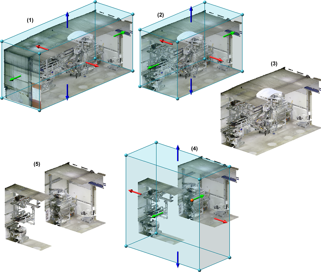
(1) Point cloud with automatic clipping box, (2) and (3) Processed clipping box and result, (4) and (5) Definition of a subtraction and result
![]() Please note:
Please note:
If a drawing created with an earlier HiCAD version is loaded with point clouds, the following will happen:
- If no clipping box is defined in the drawing, then a correspondingly large box is automatically created.
- If several clipping boxes are defined in the construction, then these are retained. These boxes can then be removed with the Delete subtraction function except for one of the boxes.
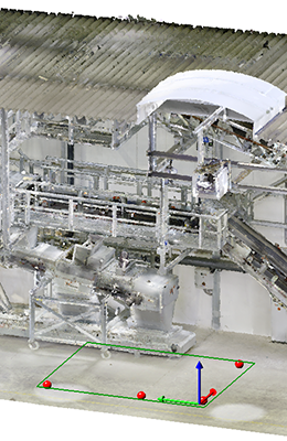
Select processing plane via points
By averaging different points of a point cloud (e.g. a wall) you create a processing plane with the new Plane from points function. You can choose the alignment of the plane freely, parallel to the plane or orthogonal to the axis.
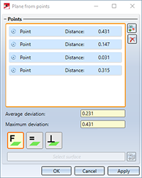
To select the points for the plane, call the function. The point selection  is active in the Free
  mode and the points are added to the list after selection. If you want to remove a point from the list, right-click on it and choose Remove from list
  .
.
As soon as you have selected more than three points, not all points have to lie exactly on the averaged plane. The Maximum deviation is the largest distance that one of the selected points in the list has to the plane. The Average deviation is the averaged value, i.e. the sum of all deviations of the points divided by the number of points.
The following options are available for aligning the plane:
|
|
Free |
As soon as you have selected three points, the plane will be displayed. By selecting further points you change the position of the plane, since the distance to each other is recalculated after each further point.
|
|
|
|
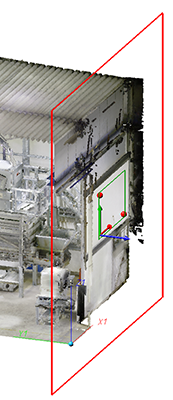
Parallel to plane |
In this mode, you first select a reference plane
|
|
|
|
Orthogonal to axis |
Here you first select the direction
|
|

 . The usual HiCAD selection for
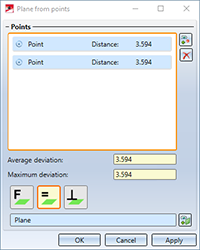

 to which the plane is to be created at right angles (90 degrees). You can determine the direction by points, an edge e.g. of an existing part or by selecting the X, Y or Z axis. The points for the new plane will then be averaged again.
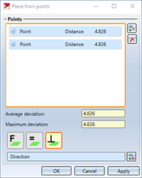
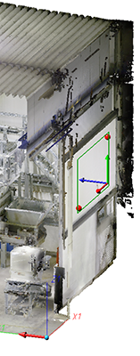
If you have entered all the required data, the plane is applied by selecting Apply or by clicking the middle mouse button. In contrast to OK, the dialogue window remains open. This way you can create more planes.
|
When determining further points for the new working plane, the position changes. The position of the plane results from the averaged points.
(1) Direction (X axis) and 2 points (2) Direction and 2 points identical to (1) plus third point |