Dimensional Constraints
Sketch > HCM > Smart dimensioning  > Dimensional constraints
Besides the  Smart dimensioning button you can find other buttons that enable you to directly create dimensional constraints for the Distance parallel to
 the X-,
  Y- or
Y- or  Z-axis. Clicking the arrow symbol of the Smart dimensioning button opens a pull-down menu with further dimensional constraints functions, e.g. for angular or radius dimensions.
When using constraints requiring a value input, you may also use formulae or variables. The start value of the variable will then be requested by HiCAD (if it has not been defined yet).
Dimensional constraints are displayed as linear, radius or angle dimensions, depending on the selected function.
| Dimensional constraints | |||
|---|---|---|---|
|
|
With this function, dimensional constraints can be set automatically. The function checks which type of element(s) has (have) been selected and automatically offers the corresponding dimensional constraints. Clicking |
||
|
|
|
Double / Diameter |
This dimensional constraint is used for dimensioning diameters in the case of revolved solid sketches. It is assigned between a symmetry axis and a point or a symmetry axis and an edge. When revolved solids are derived from sketches with this dimensional constraint, corresponding parametric dimensions are then displayed for the diameter. First, specify the symmetry axis and then identify the edges or points to be specified. |
|
|
|
Aperture angle |
Angle constraints at the aperture angle of a circular arc. Identify the arc and enter the desired angle.
|
|
|
|
This function automatically looks for distance, angle or radius constraints |
|
|
|
|
Change |
Use this function to change a constraint that has already been assigned to a c-edge. Identify the constraint you want to change and enter the new values. |
|
|
|
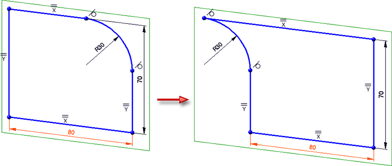
Reverse dimension direction |
Use this function to reverse the dimension direction of the constraint. In the following example, the dimension direction has been reversed for the dimension 80.
The function can only be applied to angle and distance constraints and is also available in the corresponding context menus (right click on a constraint). |
|
|
Distance parallel to X-axis |
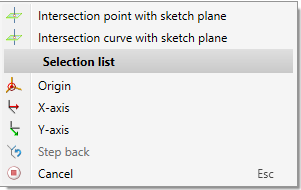
These functions enable you to assign a distance constraint between 2 points - parallel to the X-, Y- or Z-axis. The assigning of constraints to edges is only possible for planar sketches. As with the Smart dimensioning function, you can call a context menu with additional functions here:
|
|
|
|
Distance parallel to Y-axis |
||
|
|
Distance parallel to Z-axis |
||


 Please note:
- As soon as you change a first HCM distance or radius constraint in a sketch, HiCAD will offer to scale the complete sketch appropriately. For further information, please read the Auto-Scaling of Sketches topic.
- Selected HCM dimensional constraints are highlighted in the drawing by the special colour Marking 5 (default: Orange). You can change this colour via the Colour Editor if desired.
- The dimension points depend on the dimensioning option selected under 3-D HCM Tools/Settings.
- The dimensions generated by the HCM are not 'normal' HiCAD dimensionings. Conversely, HiCAD dimensionings are NOT dimensional constraints of the 3-D C-Edge Constraint Manager!
- Dimensional constraints assigned to a sketch are adopted as parametric dimensions.
- When you call one of the functions for assigning of dimensional constraints, the coordinate system for 3-D sketches will be activated automatically if the respective function works with this coordinate system. When you end the function, HiCAD will switch back to the previous coordinate system.

