LogiKal Interface
When working with the LogiKal interface, it is important to distinguish between the different tasks of HiCAD and LogiKal:
HiCAD is the ideal tool for complex spatial constructions or the detailing of connections. LogiKal, on the other hand, is an editor for windows and doors including fittings, logic checks and approval information. Window and door elements from LogiKal can be displayed and used in HiCAD thanks to the interface, just as complex façade constructions from HiCAD can be displayed and used in LogiKal the other way round. However, this interface does not work perfectly - elements from LogiKal do not necessarily contain all machining or sub-parts, such as fittings or threads, in HiCAD. However, it is guaranteed that the geometric shape and dimension of the elements is correct. For this reason, however, machining on parts should only ever be carried out in the programme that also created the parts themselves. Therefore, only the main part of elements imported from LogiKal is BOM-relevant, the sub-parts are not.
The following functionalities are available:
-
Import of new or existing LogiKal items,
-
Updating of an imported LogiKal item,
-
Subsequent modification of a sketch which is the basis of a LogiKal grid,
-
Transfer of the following processings from HiCAD to LogiKal:
-
Bore
-
Slot
-
Rectangular pocket
-
Countersink
-
Notch
-
Thread
-
-
Change of a glass element into an insert element,
-
Import of a 2-D sectional view of a LogiKal item,
-
Output of LogiKal reports directly from HiCAD,
-
Import of a profile or profile groups from the LogiKal configurator,
-
Import of glass panes,
-
Notches via LogiKal, as well as the
-
Export of a profile imported from LogiKal back to LogiKal. The following processings are also transferred:
-
Bore
-
Slot
-
Rectangular pocket
-
Countersink
-
Notch
-
Thread
-
For glass panes, only the dimensions are transferred, but not the structure. This must then be entered again in LogiKal if required.
-
The work with HiCAD is done directly in the LogiKal project. This mainly concerns the HiCAD functions:


 Insert facade + inserts from existing LogiKal project
 Change glass in insert, with LogiKal

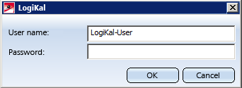
When you use these functions for the first time, you may be asked to enter your LogiKal login data.
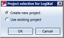
You will then asked to specify whether you want to work on an existing project, or create a new one.
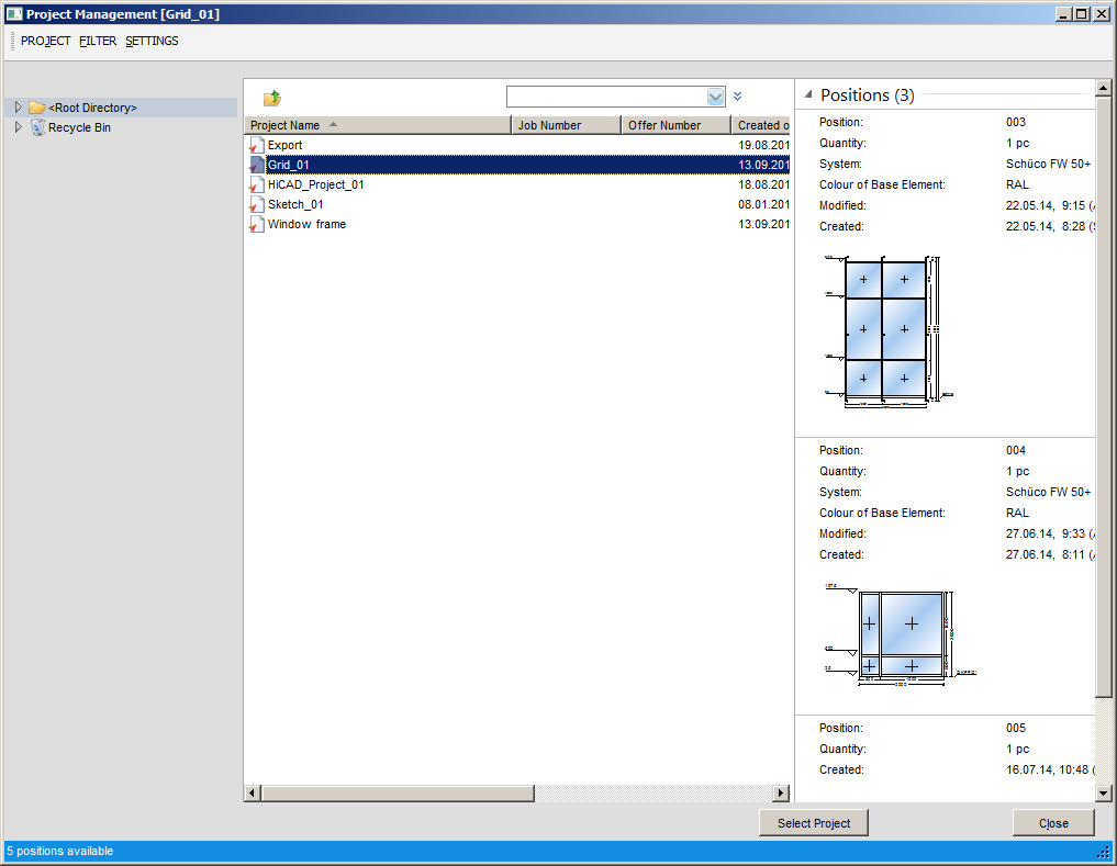
After making your selection and confirming with OK the LogiKal project management dialogue window will be displayed. If you selected the Create new project option, enter the name of the new project here; if you selected Use existing project, the selection dialogue will show all existing LogiKal projects.
Then, the LogiKal dialogue for the entering of a new item will be displayed:
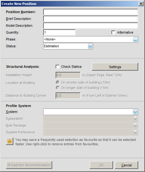
(*"Items" are called "Positions" in LogiKal)
Enter the required data, select a profile series and confirm with OK. Further LogiKal configuration dialogues for inserts will follow, which depend on the beam/profile type and the type of use.
The LogiKal data will then be transferred to HiCAD, where you will be asked to specify the Level of detail for the insertion.
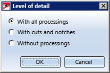
The With all processings option is useful in so far as notches can also be defined via bores, but requires more performance than the With cuts and notches and the Without processings options.
If any problems occur, e.g. with the transfer of processings, LogiKal will issue a corresponding error log.
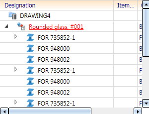
The project name (here: "Grid_01") and the item number (preceded by a #) in LogiKal are shown in the HiCAD part structure:
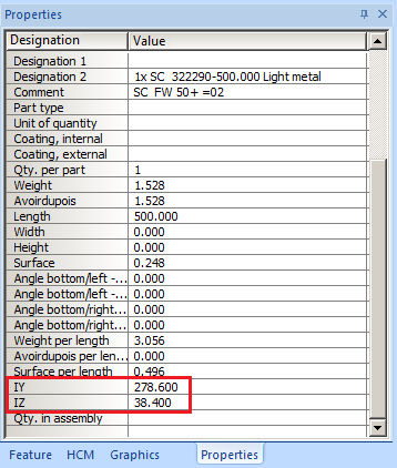
Geometry data such as moments of inertia (IY, IZ) and section moduli (WY, WZ) are taken over by HiCAD as attributes and shown in the Properties window of the ICN.
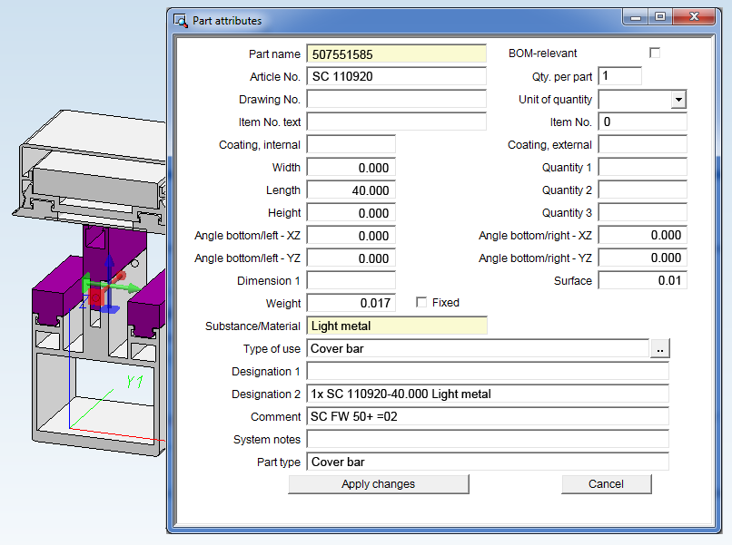
Furthermore, the HiCAD Types of use will be automatically assigned to LogiKal profiles during import.
![]() Please note:
Please note:
During installation (also Update installations) of HiCAD you can specify a directory for the installation of LogiKal in the Extended Settings dialogue window:
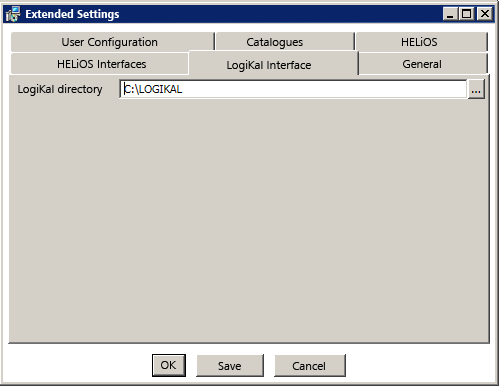
If you want to change this directory, you need to specify a valid path for HiCAD: Select Settings  > Further directories, and change the LogiKal path by double-clicking into the input field and specifying a new path.

