Sheet Metal Clamp
Civil Engineering functions docking window > Metal Engineering/Facade Engineering > 3-D Metal Engineering > Metal Engineering beam/profile connections > Sheet metal clamp
The Sheet metal clamp function allows you to connect profiles using sheet metal clamps. In practice, this method is often used to mount cladding sheets to profiles.
You can find the function in the Civil Engineering functions docking window at Metal Engineering/Facade Engineering > 3-D Metal Engineering > Metal Engineering beam/profile connections > Sheet metal clamp.
To use this function, a main assembly must be present in your drawing.
After calling the function the Sheet metal clamp dialogue window opens:
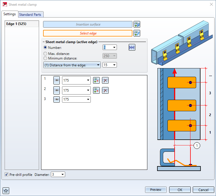
The dialogue consists of 2 tabs: Settings and Standard Parts.

Settings
On this tab you define on which surface and along which edge(s) the sheet metal clamps are to be created.
For Select insertion surface, first select the surface on which the sheet metal clamps are to be created and fastened. Then activate the function Select edge and identify in the drawing the edge of the profile to be fastened along which the clamps are to be created. You can then select further edges. These are listed in the left area of the dialogue window. You can finish the selection by pressing the middle mouse button.
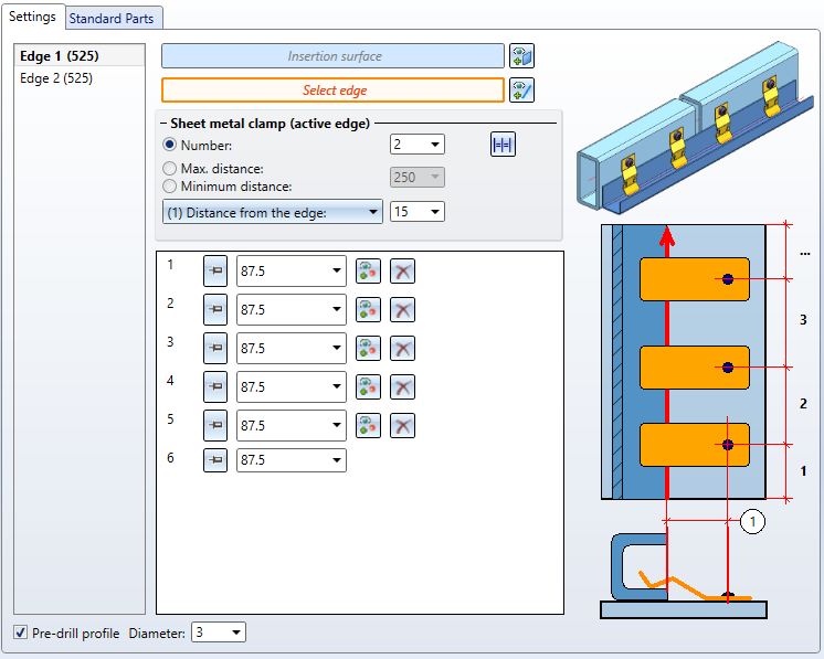
Now you can determine the positions of the individual sheet metal clamps per edge in the dialogue window. To do this, first select the edge to be processed in the left-hand area. This is highlighted in bold letters in the dialogue and in colour in the drawing.
The number or the distances of the sheet metal clamps can be determined automatically in three ways:
-
The Number option specifies how many clamps are to be created. These are then regularly distributed along the length of the edge.
-
The option Max. distance specifies a maximum distance between the clamps. As many brackets are created and regularly distributed over the length of the edge as are necessary to ensure that the distance between them does not exceed the specified value.
-
The option Minimum distance works like the option Max. distance, except that here a distance is specified that must not be fallen short of.
For the position of the sheet metal clamps on the profile, you have the choice between the options (1) Distance from the edge and (2) Distance from point in the lower drop-down menu. The distance is always measured perpendicular to the selected edge and determines the centre point of the fixing of the clamp.
-
(1) Distance from the edge specifies the distance to the selected edge.
-
For (2) Distance from point , you must identify a point to be used as a reference point for the distance measurement. If the distance is 0, the holes of the clamps will be accordingly exactly at the level of the reference point.
The respective positions of the sheet metal clamps are directly displayed in the drawing together with their number.
In the lower part of the dialogue window, the individual distances are listed in a tabular view. The distance is always measured to the previous sheet metal clamp or, in the case of the first clamp, to the beginning of the profile. If you click on a line in the table, the corresponding distance in the drawing is shown in yellow. The number in the table corresponds to the number of the sheet metal clamp that is also displayed in the drawing.
The button indicates that this value is "free", i.e. it was automatically generated from the values for number or distance of the sheet metal clamps and can be changed by them at any time. If you click on it or change the value for this distance directly, it will be replaced by the
  button to indicate that this value is "fixed" and will not be changed automatically.
Manual changes to spacing can result in automatic changes to meet the conditions for number or spacing at the top of the dialogue window. For example, if you have defined a maximum spacing and then reduce the spacing between two sheet metal clamps, this may result in the spacing between the remaining sheet metal clamps becoming too large and therefore another sheet metal clamp being inserted.
You can use the  Select reference point button to select a separate reference point for each position. First activate this function and then select the new reference point in the drawing.
The button  Delete removes a position from the list. The distance to the following position is fixed (if it is not already) and increased by the previous distance. This ensures that all positions remain in the same places and are not redistributed. If Number is selected as the distribution mode, it is also reduced by 1.
These position settings only refer to the current edge. You have the option of defining your own distances and numbers for each edge. Alternatively, you can use the  Apply settings to all edges button to apply the current settings to all edges.
The option Pre-drill profile affects all edges equally. If it is activated, holes with the specified diameter are drilled on the profile at the corresponding positions for fastening the sheet metal clamps.
Standard Parts
On this tab you can define which standard parts are to be used for Sheet metal clamps and Screws. Using the option Fit under Screws, you can control whether screws are to be inserted or not.
In the Assignment area you can choose how the created sheet metal clamps and screws are to be managed in the part structure:
-
If you select Loose part, a structural assembly Loose parts is created for each part to be clamped, which contains the respective screws and clamps. If several parts to be clamped are in a common assembly, only one structural assembly is created for this.
-
If Assembly is selected, the screws and clamps are added to the assembly of the profile.
