"Mullion Connection" Design Variant
"Civil Engineering functions" docking window > Metal Engineering/Facade Engineering> 3-D Metal Engineering > Metal Engineering beam/profile connections > Mullion connection (1314)
In the Civil Engineering functions docking window (at the right hand side of the HiCAD screen) you will find the Metal Engineering / Facade Engineering menu item which in turn contains all Metal Engineering Design Variants.
One of these variants is the Mullion connection (1314).
This variant enables you to connect two Metal Engineering series beams along a beam axis. This can take place either by means of a visible, lateral bolting, or from the top by mean of a bolting which is invisible from the outside. Single parts of the bolting can also be inserted with an offset or with specified distances from the connection. Furthermore, it is possible to bolt the insertion profile to only one mullion profile (e.g. as a compensation for thermal expansion).
After selecting the Mullion connection (1314) function in the Civil Engineering functions docking window, identify the two beams you want to connect.
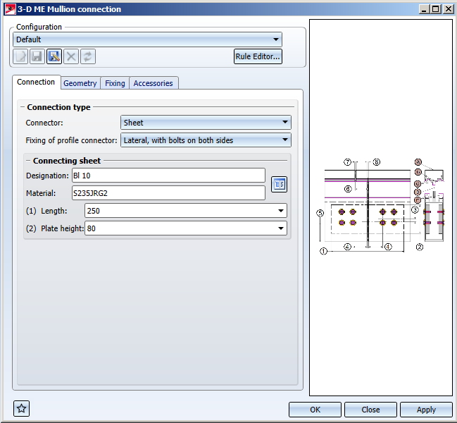
A dialogue window with the following tabs will be displayed:
The settings in the dialogue window can be saved as Favourites and reused at any time. To do this, click on the  at the bottom left of the window to activate the context menu. More about Favourites management can be found in the Manage Favourites topics of the HiCAD Basics Help.

Connection
Favourites
The settings in the dialogue window can be saved as Favourites and reused at any time. To do this, click on the at the bottom left of the window to activate the context menu. More about Favourites management can be found in the Manage Favourites topics of the HiCAD Basics Help.
On the Connection tab you can select whether the Fixing of profile connector is to be made
- From top
- Lateral, with bolts on both sides, or
- Lateral, with through bolting.
Depending on whether you have chosen Sheet, Hollow profile or Series beams as Connector from the selection field, further options will be offered under the caption Connecting sheet, Hollow profile or Series beams. For sheets, only the Lateral, with bolts on both sides connection option will be possible.
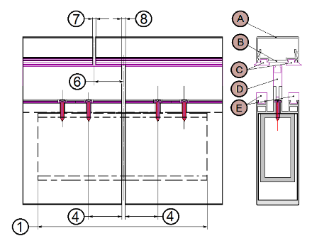
Hollow profile, connectors from top
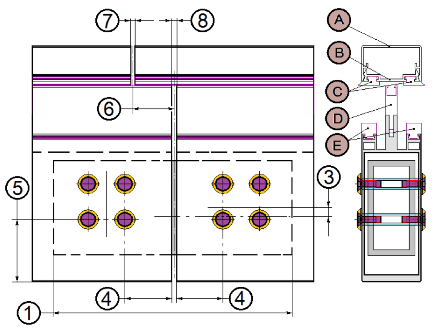
Hollow profile, connectors lateral with bolts on both sides
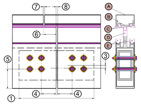
Hollow profile, connectors lateral with through boltings
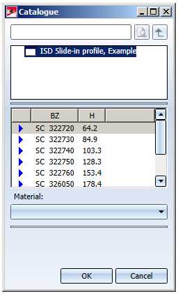
On the Connection tab you can select Sheets, Series beams or Hollow profiles via a catalogue. To do this, click on the  icon. For Sheets you can also change the length in the input field (if you select a flat steel from the catalogue, the selection field for the height will not be available, as the height has already been specified for the part).
Eight FW 50+ slide-in profiles are available as Series beams in the catalogue.
Geometry
On the Geometry tab you can specify further attributes of the connection. In the graphic on the right hand side you can see for which geometry a corresponding value can be assigned in the dialogue field (appropriate numbers and letters appear in brackets in the corresponding menu items).
- Placing of connector: You can choose between the options Top, Bottom, or Centred with offset (or with the value 0 as Offset for the Centred with offset option, if you want to place the connector centred without offset, in the direction along the joint).
- Joint: Here you can define the Offset and the Clearance for a Cover strip, Contact profile, Gasket(en) (clearances between mullion profiles and cover strips can differ), and an Isolator , and specify the clearances between the two profiles via Clearance, Profile.
- Fixing of connector : You can choose between the options With both profiles and Only with 1st profile. Furthermore, you can specify a Distance from joint and an Offset for the fixing.
- Bore grid: Here you specify the position of the grid / profile reference points for the bore. You can select a horizontal and vertical position for the Grid centre, or select one particular bore row (vertical: bottom row, horizontal: first row seen from joint). The Reference point on the beam can be set on the Bottom edge of profile, and in the Centre of hollow (of the profile).
- For Grid X and Grid Y ( X- or Y-direction of the grid in the top view) you can specify the number of bores. The distances between the bores can be assigned individually (the corresponding number of input fields match the specified number of bores), or, if you want to have equal distances, use the Change all option to set the same distance value for all bores in one direction.
Fixing and Accessories
On the Fixing tab you can change the Bolt and the Washer of the bolted connection via the catalogue.
On the Accessories tab you can add further materials to the Design Variant by clicking on +, or remove them from the list by marking them and clicking on -.
When you close the window with OK, the mullion connection will be applied to the two profiles in your drawing.
![]() Please note:
Please note:
In the graphics window on the right, changed options will be displayed.
