Feature Technology - What's New?

Service Pack 2 2022 (V 2702)
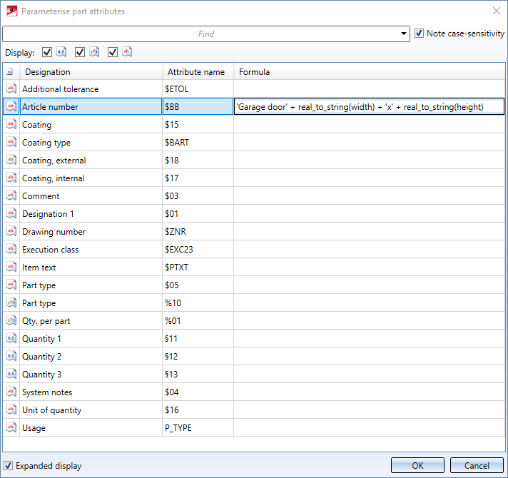
Parameterise part attributes
The function Parameterise part attributes  has been further expanded.
-
The attributes in the dialogue window are now displayed in groups, e.g. System attributes, Properties, User-defined attributes, etc. This provides a clearer overview.
- As with line types, edge colours can now also be parameterised.
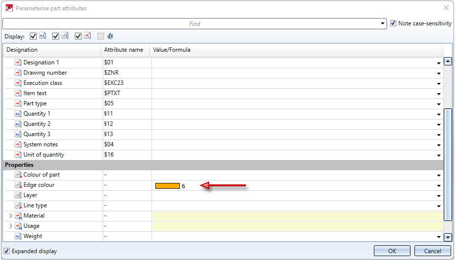
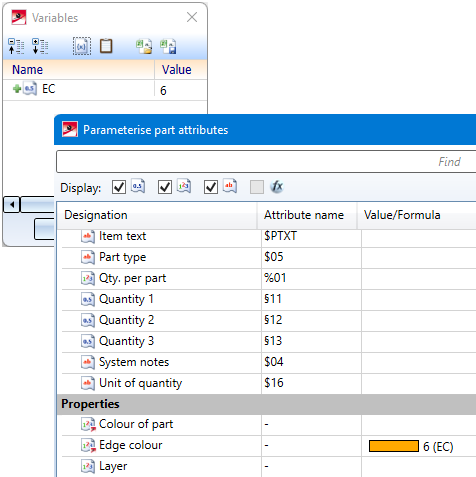
If you want to parameterise the edge colour, for example, enter either the colour number or a variable, e.g. EC (for Edge Colour), as a constant formula. When using variables, please note that they must be defined beforehand.
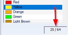
You can see which colour has which colour number in the Colour Editor. The colour number of the selected colour is displayed below the colour list, e.g.:
Please note:
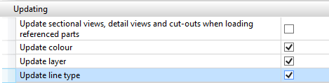
The edge colour of a part, the line type and the layer can also be parameterised. However, this only applies if the corresponding checkboxes are active in the Configuration Editor at System settings > Referencing. This also applies to non-referenced parts!
- For referenced parts the settings that are set in configuration management at System settings > Referencing > Updating are taken into account as of SP2. This means that the settings defined under Synchronization of attributes are not only taken into account when updating referenced parts, but also when parameterising part attributes of referenced parts. For referenced parts, only those attributes are offered that are transferred with the part via referencing. Otherwise, the attributes that are transferred with the superordinate assembly are added.
A simple example:
The attribute number per part is to be adjusted for referenced parts only for secondary parts. The table in configuration management has been changed accordingly.
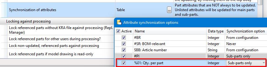
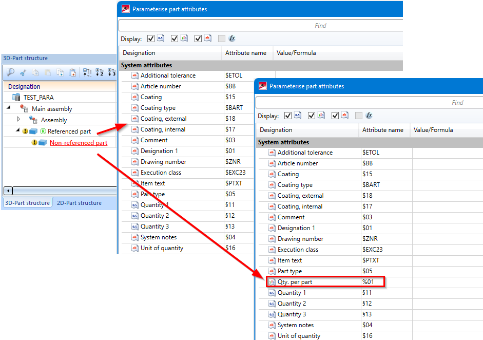
When the Parameterise part attributes function is then called for a referenced part, the attribute Qty. per part is not available, so it cannot be parameterised.
However, if the referenced part contains, for example, a non-referenced sub-part, then the attribute can be parameterised for this auxiliary part and, for example, also for the superordinate assembly.
Please note:
If a part with parameterised attributes is subsequently referenced, the parameterisation can become invalid. In this case, the respective attribute - provided you have editing rights for this attribute - is calculated and set, but the parameterisation is lost.
New function cat_item_id(...)
With cat_item_id a new 3-D function is available in the feature area. The function searches a table in the catalogue according to any criteria and returns - in contrast to the item_id function - not the row index but the Data record ID of the first item found as the result.
Syntax
cat_item_id('table';('column';'value');('column2';'value2');...)
catalogue_item_id('table';('column';'value');('column2';'value2');...)
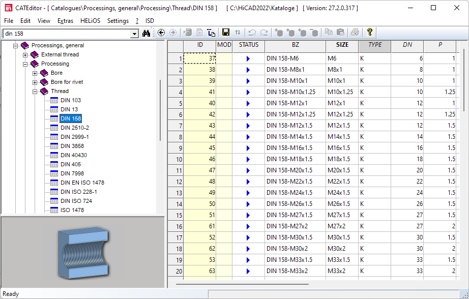
The first parameter is the internal name of the table to be searched in the catalogue. You get this by right-clicking the desired table in the Catalogue Editor and selecting the entry Change alias name in the context menu. The internal name of the table is then displayed in the Entry field in the dialogue box that appears. You can then close this dialogue by clicking on the Cancel button.
An example:
As an example, consider the table displayed.
|
Formula |
Result |
|---|---|
|
|
40 |
|
|
43 |
|
|
5 |
Service Pack 1 2022 (V 2701)
Icons for features adapted
For individual functions, there were previously differences between the icons in the feature and in the menu bar. The icons from the menu bar are now also used in the feature.
Dependent part for internally referenced parts
In addition to externally referenced parts, from HiCAD 2022 SP1 you can also derive dependent parts from internally referenced parts.
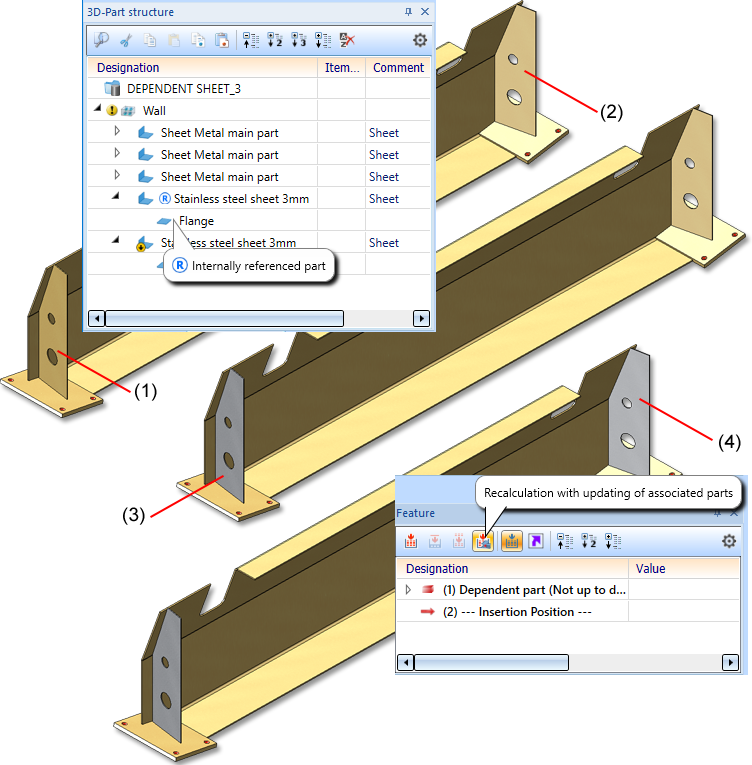
(1) Internally referenced part, (2) Dependent part
(3) Colour of internally referenced part changed
(4) Feature for dependent part recalculated
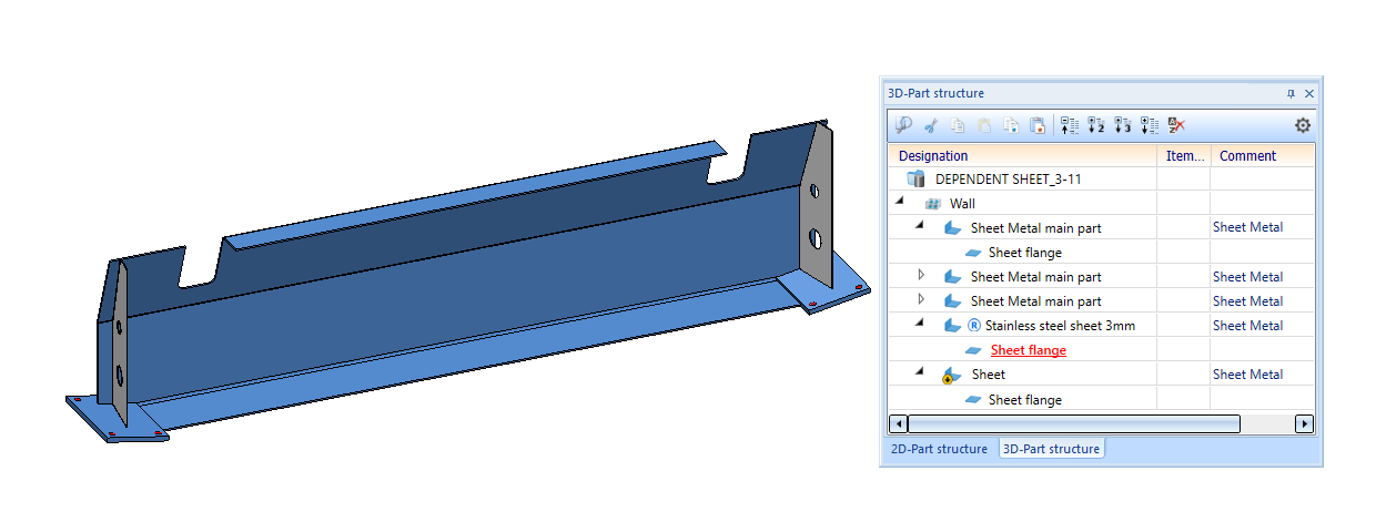
Dependent part for internally referenced parts
From HiCAD 2022 SP1 you can now also create dependent parts for internally referenced parts.
Parameterise part attributes
As of HiCAD 2022 SP1, you can also call the Parameterise part attributes function via the feature log.
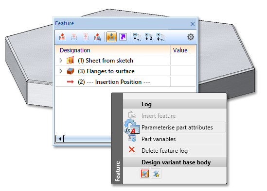
If the feature log already has a Set attributes entry for the part attributes, you can either modify the existing one or create a new feature.
In the dialogue, the Value has been added to the Formula column. The value comes first and is the evaluation of the formula. If you change the formula, the value is updated. With a click of the right mouse button you call up the Formula Editor.
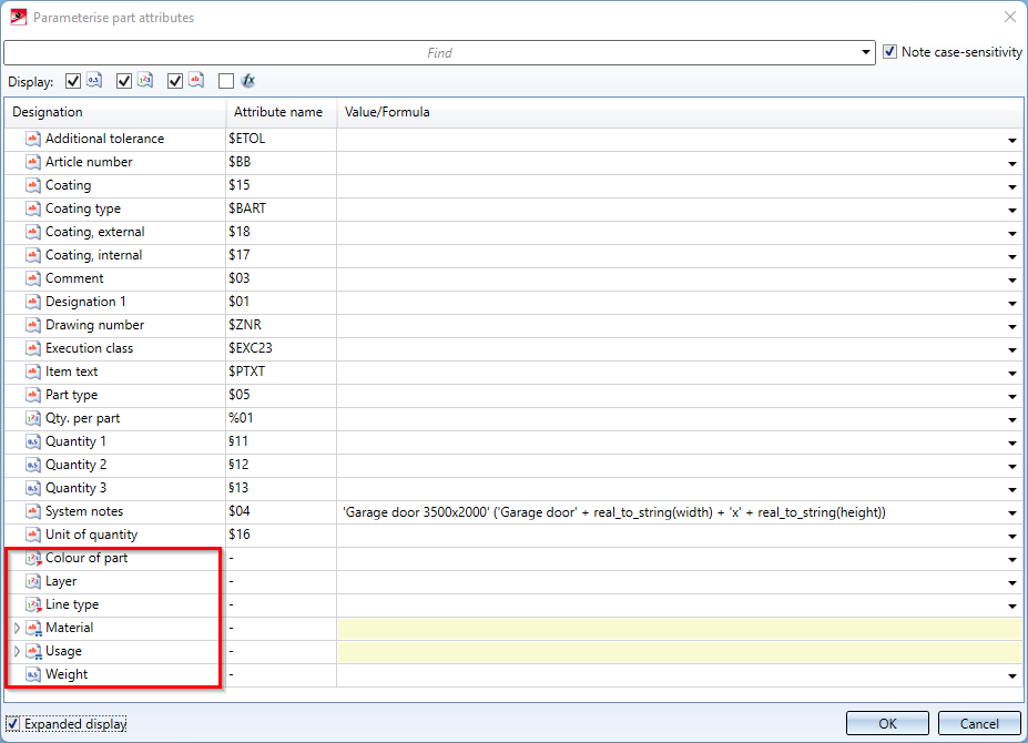
Furthermore, the following parameterisable properties have been added:
- Colour of the part,
- Layer,
- Line type,
- Material,
- Usage, and
- Weight.
For the parameterisation of the attributes Material and Usage, the respective entries Catalogue and ID must be parameterised. These IDs correspond to the unique assignment in the catalogue.
- Catalogue: Corresponds to the Catalogue ID
- ID: Corresponds to the Item ID
User-defined system attributes
If the user has entered own/additional attributes in the catalogue at System settings > System attributes, these are also listed in the dialogue
Major Release 2022 (V 2700)
Parameterise part attributes
As of HiCAD 2022, it is also possible to parameterise part attributes such as Article number, Quantity 1 or the Development width via formulas using the function Parameterise part attributes .
The parameterised attributes can still be changed afterwards via the function Part attributes, but will then be overwritten again when the feature is recalculated.
Deselect feature steps
If one or more feature steps are selected in the feature area of the ICN, these can also be deselected in analogy to the behaviour in other places by clicking on an empty area of the Graphic window.
Support of multi-line formulas
In the Formula Editor, it is now possible to enter formulas in multiple lines. This has no influence on the calculations performed, but complex formulas can be entered much more clearly this way.
An example is a formula that takes on a different value depending on the value of a variable. In a single line, this formula would look as follows:
ext_cutout_top_first_type='Type 39'?26:(ext_cutout_top_first_type='Type 48'?49:(ext_cutout_top_first_type='Type 51'?49:(ext_cutout_top_first_type='Type 58'?72:(ext_cutout_top_first_type='Type 2351'?49:500))))
Split into several lines, it would look like this:
ext_cutout_top_first_type = 'Type 39' ? 26:(
ext_cutout_top_first_type = 'Type 48' ? 49:(
ext_cutout_top_first_type = 'Type 51' ? 49:(
ext_cutout_top_first_type = 'Type 58' ? 72:(
ext_cutout_top_first_type = 'Type 2351'? 49: 500
))))
To do this, line breaks can be inserted in the formula editor using the SHIFT+ENTER key combination.
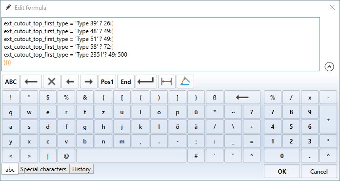
In addition, the size of the Formula Editor window can also be changed vertically to be able to display formulas with many lines completely. Furthermore, the keyboard can be hidden and shown again via the arrow symbol next to the text input field or via the key combination Alt+Page Up or Alt+Page Down.
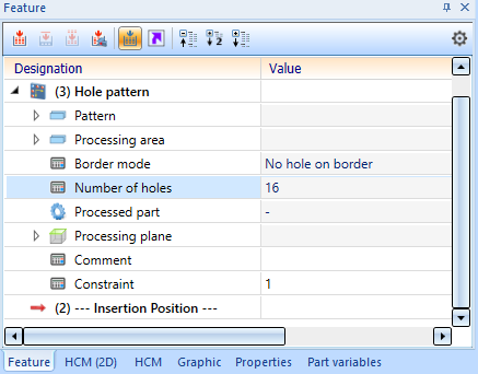
Hole pattern: Number of holes
For Hole patterns that were created using the same-named function, the Number of holes attribute is now displayed in the feature entry, indicating how many holes were created by this hole pattern. Holes that were only partially created (e.g. because they are located on the border of the processing area) are counted as normal.