Elements that are installed with the help of the Element installation function must often be hanged on a sub-structure or be fixed to it.
The Sub-structure function allows you to place profiles on sketch lines, just as you would do with the Element installation function.
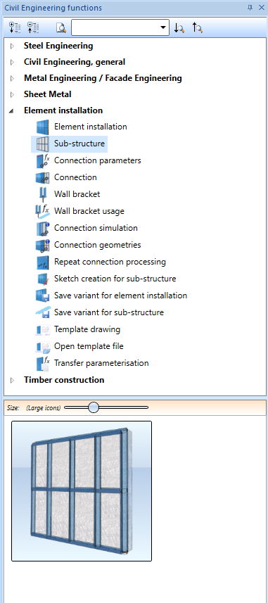
You find this function in the Civil Engineering functions docking window beneath Element installation.
When you call the function, the Sub-structures window opens:
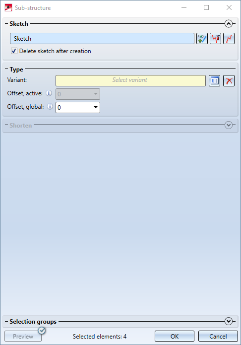
HiCAD prompts you to identify a sketch (this step will be omitted if a sketch has already been selected when the function was called).
Alternatively, you can call the functions  Select sketch,
  Process sketch and
  New sketch in plane via the corresponding buttons.
![]() Important:
Important:
This function works only for sketches that are exclusively made up of straight lines. The function cannot be applied to sketches containing curves, circular arcs or circles.

Select profiles
You can now individually assign a profile to each sketch element.
In the drawing, the sketch elements are highlighted in a different colour:
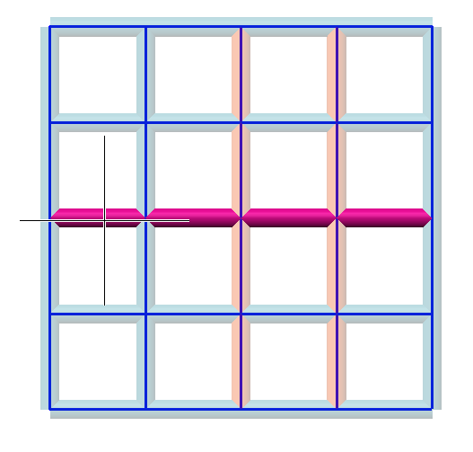
The colours have the following meaning:
 The line element on which the cursor points is highlighted in violet.
 Currently selected line elements are highlighted in orange.
 All other line elements are highlighted in light blue.
You can select line elements as follows:
- Immediately after calling the Sub-structure function, all line elements are selected.
- You select individual line elements by clicking them (LMB).
- You select all line elements in a rectangle by right-clicking on the model drawing, choosing Select in rectangle and drawing a rectangle around the desired line elements.
You can also press and hold down the CTRL key and draw the rectangle, without choosing the Select in rectangle function.
- When you click a line element while holding down the CTRL key, it will change its status: A selected line element will no longer be selected after the mouse click; conversely, an unselected line element will be selected afterwards. Please note that at least one line element must always be selected. If this is not the case, an error message will be displayed.
Settings for line elements
The following setting are possible for the selected line elements:
|
Variant |
Here you can choose the variant that you want to use for these line elements. Click |
|
Offset, active |
Here you can define the distance between the generated profiles to the sketch. In case of positive values the beam is located above the sketch, in case of negative values below the sketch. |
|
Offset, global |
Like Offset, active this value determines the distance of the generated profiles to the sketch. While Offset, active applies only to the currently selected profiles, Offset, global defines one offset for all profiles of this sub-structure. |
|
Shortening of start and end |
The selected profiles can be shortened at their start (bottom) or end (top) by the specified values. The setting can be defined separately for each line element. |
|
Variables list |
Depending on the chosen variant, you can adjust the associated variables here. This area of the window can also be customized if desired. |

With the exception of Offset, global, these settings always refer only to the currently selected line elements.
Calculate
When you click OK the sub-structure will be created. During calculation the  symbol will be shown in the dialogue window.
If any errors occur during calculation, this will be indicated by the  symbol on the OK button. If you move the cursor over this symbol, a short error description will be displayed.
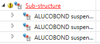
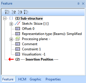
The created profiles will be placed beneath a new assembly called Sub-structure.
This assembly also contains the Sub-structure Feature. If you double-click this Feature, a dialogue window will be displayed, enabling you to change this sub-structure.
Creation of previews
Use the  button to activate or deactivate the generation of previews. By default, the checkbox is active, that is, a new preview will be generated each time you change an entry in the dialogue window.
For a more fluent working with large sub-structures you can remove the checkmark from the button. After this, a preview will only be displayed if you explicitly click on the button (i.e. previews will no longer be generated automatically).
Connecting sub-structure and element installation
Use the Connection function to mount sub-structures and installed elements together. This enables you to apply adjustments to both assemblies, e.g. to insert bores and boltings.
Re-generating the sub-structure
Adjustments made by hand to a substructure, e.g. bores, are retained even after the sub-structure has been recalculated. In case you want to discard your changes, use the Create new function in the context menu of the Sub-structure entry in the Feature log.

Create Own Profiles for Sub-structures • Customizing the Dialogue Window