The Element installation module (for which you need a separate license) provides you with a multitude of Eternit installation elements. In addition, a wide range of Eternit semi-finished products allows an effortless integration of the desired surface and colour variants.
An interface to the production department can be created by adding the ALUCOBOND®-specific allowance methods to the production data in HiCAD and passing them automatically to the CNC machines in the production department (see also the HiCAD Sheet Metal Help).
Eternit installation elements
Eternit panels can be installed on any rectangular, triangular or polygonal sketch areas.
Please remember:
Which installation elements are available depends on which HiiCAD software license you use.
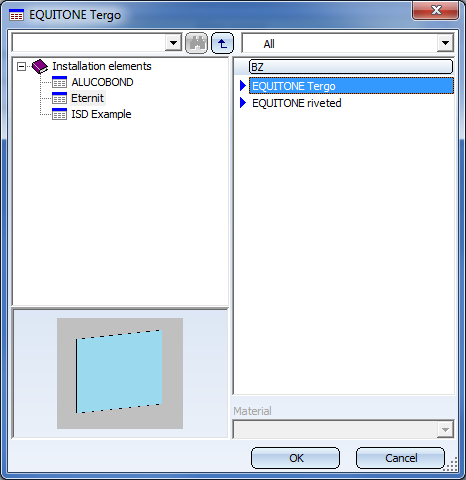
Eternit installation elements can be found in the catalogue Factory standards > Installation Planning - Parts and Processings > Element installation > Installation elements > Eternit:
The elements for sub-structures can be found in the catalogue Factory standards > Installation Planning - Parts and Processings > Sub-structure > Installation elements > Eternit:
Available are:
- Riveted to L-profile
- Riveted to T-profle and
- Systea UBE 25/2

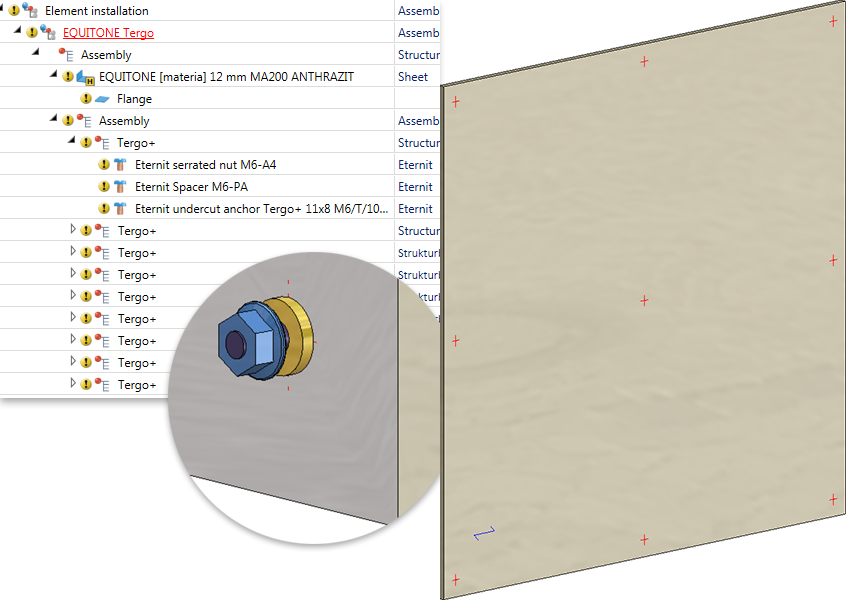
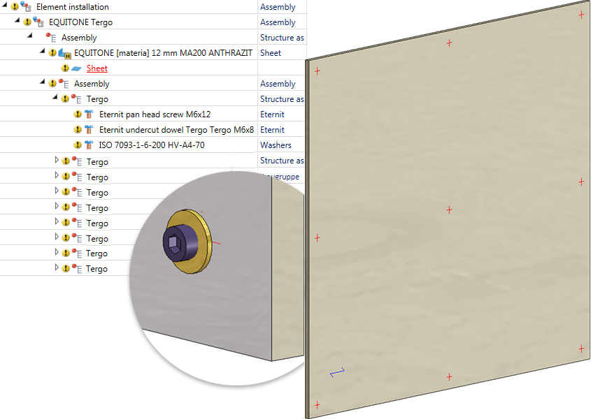
EQUITONE Tergo
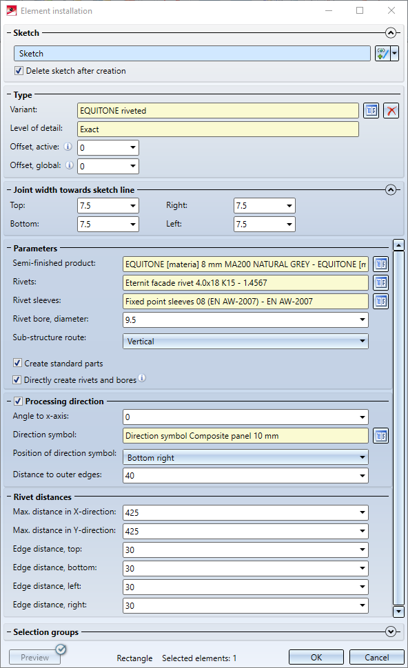
Für Eternit-Platten vom Typ EQUITONE Tergo stehen im Dialogfenster folgende Einstellungsmöglichkeiten zur Verfügung.
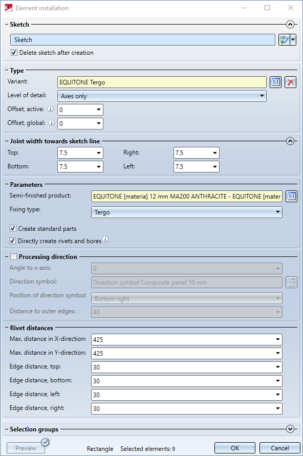
Parameters
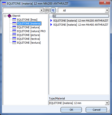
Here you choose the deired semi-finished product and the fixing type - Tergo+ or Tergo.
Furthermore, you can choose here whether standard parts (for fastening) should be installed or not. The ISD default setting is that standard parts are created, i.e. the checkbox is active. If the checkbox is inactive, the standard parts are not listed in the bill of materials.
If the rivets and bores are to be generated directly, the corresponding checkbox must be activated. Alternatively you can - by deactivating the corresponding checkbox - specify that the rivets and bores are created by mounting to the sub-structure.
Processing direction
Here you determine the data for the processing direction. These are:
- the processing direction by specifying the desired angle
- the symbol for the processing direction
- the position of the processing direction. Possible are middle, bottom left, bottom right, top left and top right.
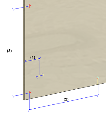
- the distance of the direction symbol to the outer edges (1).
Rivet distances
Here you define the maximum distance between the fixing elements in horizontal (2) and vertical direction (3) and the edge distances top/bottom/left/right.
Example with fixing type Tergo+
Beispiel mit Befestigungsart Tergo
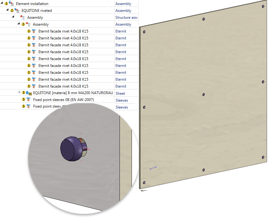
EQUITONE riveted
For Eternit panels of the type EQUITONE riveted the following setting options are available:
The dialogue window is largely operated in the same way as the one for EQUITONE Tergo, with the difference that you do no choose the fixing type here, but the required rivet, the matching sleeves and the diameter of the bores for the rivets.