Sheet Metal > New > FromSol 
With the Sheet from solid function you can generate a sheet from a 3-D part. The 3-D part must have a uniform thickness that is acceptable for sheets. The article number is taken from the existing article number of the imported STEP part or the 3-D part, for example.
Proceed as follows:
- Activate the function.
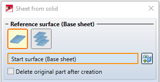
The Sheet from solid dialogue window appears.

Two options are available for the reference surface for the base sheet:
|
|
If this icon is active, you can select a base area for the new sheet metal part.
If you want to identify a different surface, click on the |
|
|
With this icon you can collect several 3-D parts in a list and then convert them all into sheet metal parts.
Right-click on a solid to remove it from the list. If you want to select additional parts, click on the If you have activated an assembly or several main parts in the ICN before calling the function, these parts appear in the list of active parts. |

 icon for identifying the base surface.

 icon for identification.
- Identify the base area or several parts.
For starting parts without a planar surface, without solid or sheet metal parts, the error message: No planar surface in the transferred part appears. In the case of a tetrahedron, a surface can be selected manually after automatic selection has failed.
With the option Delete original part... the 3-D part is deleted as soon as the sheet metal has been constructed from it. In the ICN the entry of the 3-D part is also deleted.
- Select the mode for the sheet thickness.
|
Sheet thickness from semi-finished product |
In this mode you select the sheet thickness with semi-finished product. |
|
Automatic sheet thickness from semi-finished product |
The sheet thickness is automatically selected to match the selected semi-finished product. |
|
Sheet thickness, from solid |
The sheet thickness is taken from the solid. |
|
Sheet thickness, value input |
The sheet thickness is entered directly. |
- Enter the sheet thickness or choose a semi-finished product.
You can adopt the standard for semi-finished products by activating the  icon from the Catalogue Editor. The selection of a semi-finished product influences the sheet thickness, the material and the article number. To change the article number, deactivate the checkbox in the General area and enter the desired name there.
Select Adjust bend zones to automatically edit corners from the 3D solid so that the sheet metal parts abut cleanly. You can achieve the same effect with the Cut off corner function.
Activate the Referenced checkbox if the base sheet is to be saved as referenced (see HiCAD 3-D).
A frequently used part should be saved referenced. The part is then additionally saved as a single part at the end of the function sequence and is not permanently integrated into the drawing. If you change the part, you can update the part in the model drawing.
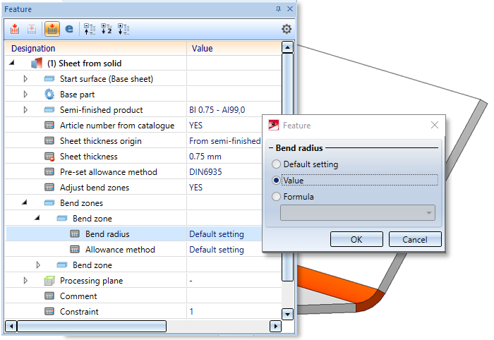
To disable the features when you create the sheet metal part, deactivate the checkbox ![]() . Feature technology is active
. Feature technology is active ![]() by default. For example, you can use the feature log to change the radius of bend zones later.
by default. For example, you can use the feature log to change the radius of bend zones later.
If Semi-finished product is activated, the article number of the sheet is loaded from the catalogue if the checkbox behind Article number is activated. Otherwise, you can enter your own name in the text field or use the name of the solid.
- Accept the generated sheet metal part with OK.
Once you have entered all the necessary data, the new sheet can be generated. If you select Apply the sheet is inserted, but the dialogue window remains open (unlike OK, which closes the dialogue window). This way you can change the data and generate a new sheet by clicking on Apply or the MMB. If you exit the dialogue window with Cancel, the function is cancelled without inserting the sheet or applying any changes.
Incorrect entries are marked with this  symbol. Move the cursor over the symbol to display the error message. If the function cannot be executed with the entered data, this
  symbol appears on the OK button . Move the cursor over the symbol to display the error message.
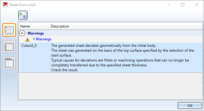
If deviations from the initial geometric body occur during generation, these are listed after the sheet metal parts have been generated.
![]() Please note:
Please note:
- When an itemised solid is converted to a base sheet, the item number will be transferred. The BOM-relevance depends on the setting in the Configuration Editor at Sheet Metal > Default setting > Sheets/plates BOM-relevant.
- Please note that not all processings can be transferred when using the Sheet from solid function.
- Double-click on the Sheet from solid feature to open the dialogue window for creating the sheet metal part. Here you can then set or remove the checkmark for semi-finished part, for example.

