Drawing > Itemisation/Detailing > Item.  > Change parameters
Drawing > Itemisation/Detailing > Item. > ... with options 
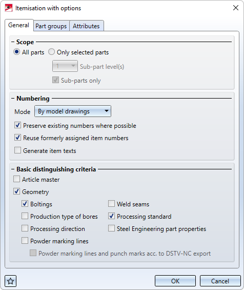
On the General tab you specify:
- which parts are to be itemized,
- how the numbering is to be done,
- whether itemisation texts are to be generated and
- which distinguishing criteria are to be used for identical part search.

Scope
Here you select the parts that you want to be itemized and checked for equality in the identical part search. Possible are:
- All parts or
- Only selected parts, e.g. several assemblies.
If the Only selected parts has been chosen, you have the additional option to select the number of the sub-part levels to be taken into account for itemisation. If you want only sub-parts to be considered, activate the same-named checkbox.
Example:
The original drawing (left) consists of several assemblies, of which only the selected ones (right) are to be itemized (all parts are BOM-relevant. Favourite: Steel Engineering).
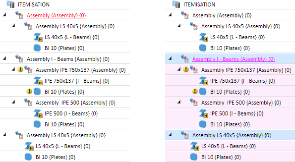
The result of the itemisation carried out with the option Only selected parts and selection of the sub-part levels 0, 1 and 2
Numbering
Here you specify how the numbering is to be done and whether an itemisation text is to be generated.
Mode
Currently, follwings modes are available:
- By model drawings
The numbering is continuous for the entire drawing. - By assemblies
The numbering takes place continuously within an assembly. The same parts that exist a number of times in different assemblies may have different item numbers. - By top level assemblies
In this mode, only the first sub-part level of the main assembly is considered. This mode is also possible if a unique, BOM-relevant top-level assembly exists instead of the main assembly.
Important:
If this mode is used when converting previous itemisations, then no sub-assemblies are converted.
Examples
In the following illustration, the factory settings for steel engineering have been used.
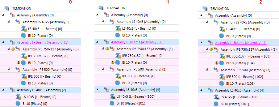
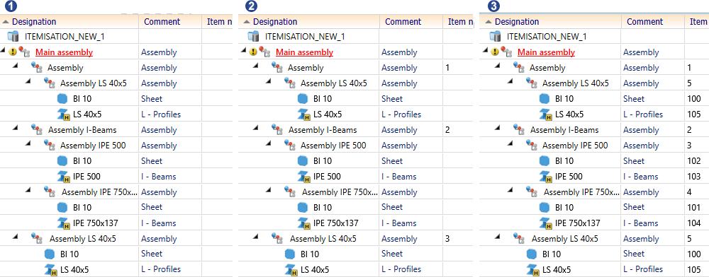
Example 1
(1) Without item numbers; (2) Itemised in the mode By assemblies; (3) Itemised in the mode By model drawings
Example 2
Here a main assembly is used.
(1) Without item numbers; (2) Itemised in the mode By assemblies; (3) Itemised in the mode By model drawings
Preserve existing numbers where possible
If the checkbox is inactive, all parts are itemised again.
In connection with this setting, please also note the notes on changing the BOM relevance of positioned parts.
Example:
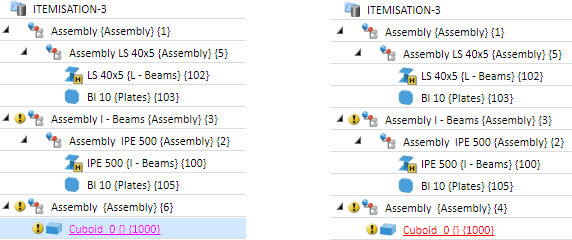
The left image shows the original drawing with various, already itemized parts and assemblies (all parts are BOM-relevant. Favourite: Steel Engineering). On the right hand side the original model drawing has been modified by mounting a plate onto the IPE 500 beam. Furthermore, another assembly has been assigned as a sub-part to the assembly LS 40x5. The plate and the new assembly have not been itemized yet.
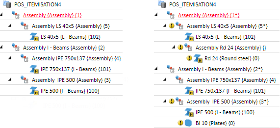
The following image shows the difference in itemization when the Preserve existing numbers where possible checkbox is inactive (left) and active (right).
Assign previously assigned item numbers again
If this checkbox is activated, previously assigned numbers, e.g. after deletion of parts/assemblies, will be assigned again, if this will not lead to conflicts. This checkbox is available only if the Mode: By model drawings or By top level assemblies has been selected beneath Numbering.
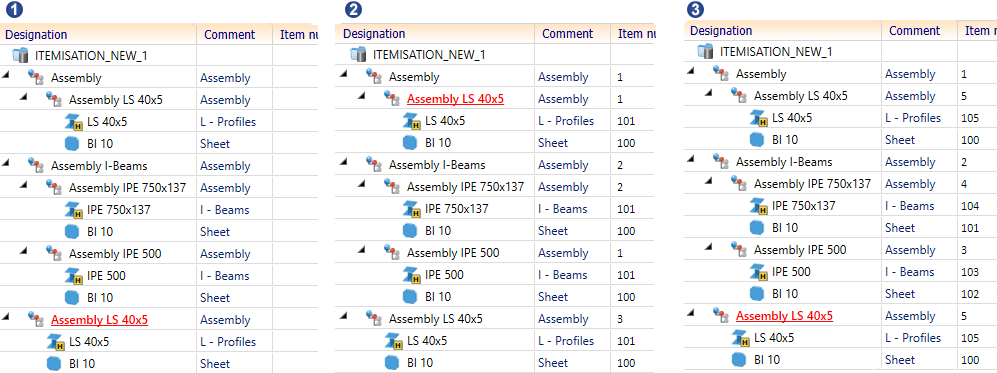
Example:
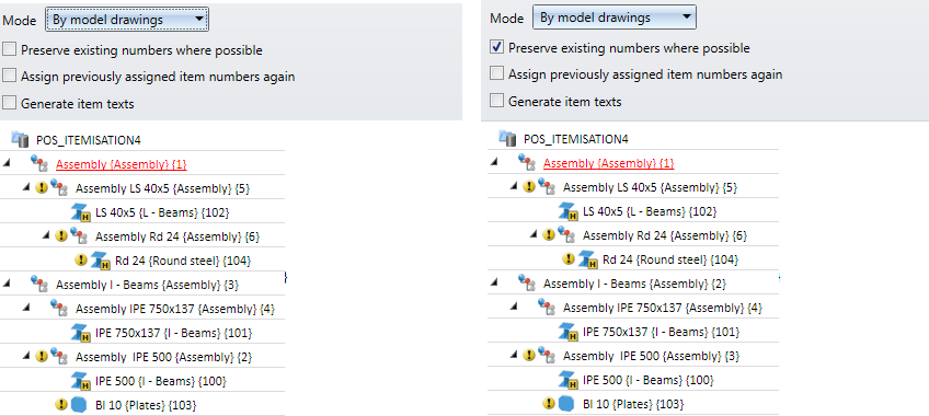
The left image shows the itemized drawing. On the right hand side, the assembly with item number 4 has been deleted and a new assembly has been added. (All parts are BOM-relevant. Favourite Steel engineering)
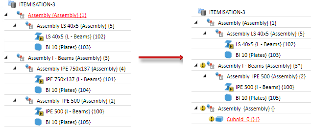
Now, the itemisation is performed with the Only new and changed parts option. The image on the left shows the result without activation of the Assign previously assigned item numbers again checkbox. The item number 4 (of the deleted assembly) has not been assigned here again. On the right hand side you can see the result with activation of the checkbox.
Generate itemisation texts
In addition to the (integer) item number, you can also generate an itemisation text. It may consist of free texts and attributes from different HiCAD/HELiOS sources. If you want these texts to be generated automatically, activate this checkbox. The configuration of the itemisation texts takes place on the Part groups tab.
Itemisation texts are assigned to the part attribute $PTXT.
Basic distinguishing criteria
Here you determine which criteria are to be taken into account for the identical part search.
Article master
If this checkbox is active, the HELiOS article attributes are also taken into account in the identical part search. When using the Drawing Management module, the settings of the Article master, itemisation function are also taken into account.
Geometry
Here you define whether a identical part search is to be carried out and which components are to be taken into account. Permitted components are:
- boltings,
- weld seams,
- the production type of bores,
- the processing standard,
- the properties of Steel Engineering parts,
- the processing direction,
- powder marking lines, and
- powder marking lines and punch marks according to DSTV-NC output (only if an appropriate license exists).
![]() Please note:
Please note:
- Processing direction
- Only direction symbols on cover facets of sheet metal flanges and steel engineering plates are taken into account.
- Only their (developed) directions and their RTYP (1: one-sided, 2: two-sided) stored in the catalogue are relevant for the comparison of processing directions.
- Irrelevant for the comparison are therefore in particular the position of the direction symbols (on which plate, where on the plate) and their geometry.
- Bores - also those created as subtraction - are considered identical even if they have different representations. An exception are bores that are only represented as axes.
- If bores and corresponding processings are to be considered identical only if their catalogue/table IDs match, you can achieve this by activating the Processing standard checkbox.
- Variable through holes are considered to be equal even if the holes were drilled in opposite directions and the base points do not match. An exception are variable through holes that are only displayed as axes.
|
Important:
|
Examples
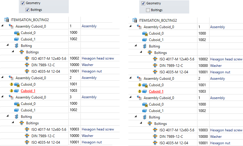
The image below shows a drawing with 3 assemblies that differ with regard to their boltings, but have an identical geometry.
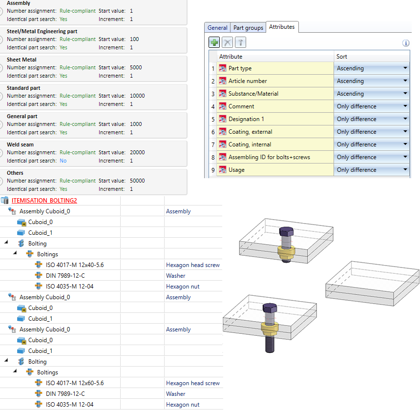
The drawing is to be itemized with geometric identical part search - once with activated, once with deactivated Boltings checkbox.
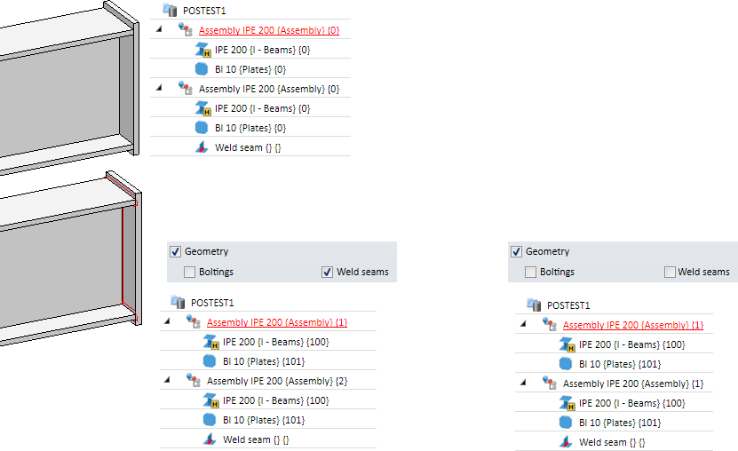
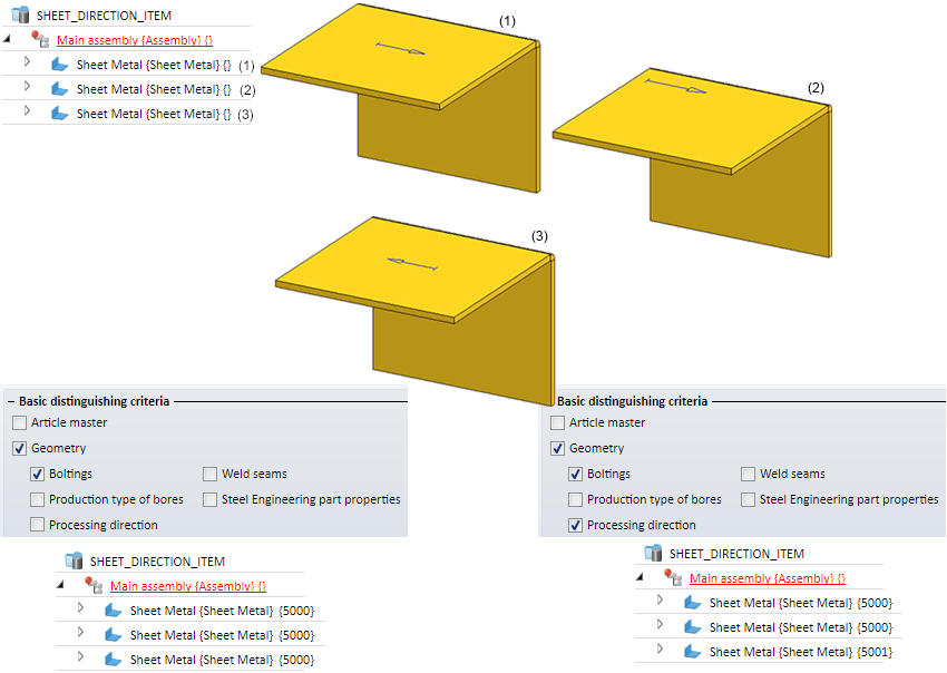
Example - Processing direction
The image shows three geometrically identical plates. All sheets have a symbol for the processing direction, but only Sheet 1 is assigned to a cover facet. If the Processing direction checkbox is deactivated during itemisation, all sheets receive the same item number. If, on the other hand, the checkbox is active, then Sheet 2 and Sheet 3 receive the same item number. Both are considered to be the same because the symbol for Sheet 2 is not assigned to a cover facet.
The image below shows 5 sheet metal parts with one bore (Diameter: 32). Bore 1 to 3 have been created with the function Bores/Threads, Bore 4 with the function Subtract part, via translation:
(1) Representation with bore and axes.
(2) Display without axes
(3) Display with axis only
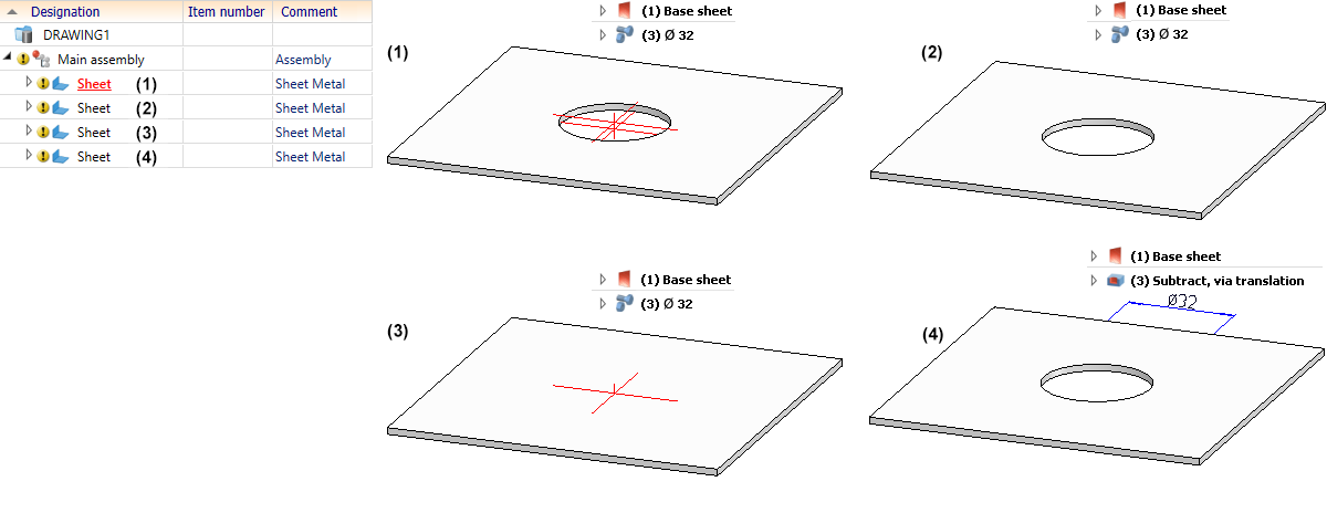
The itemisation yields the following results:
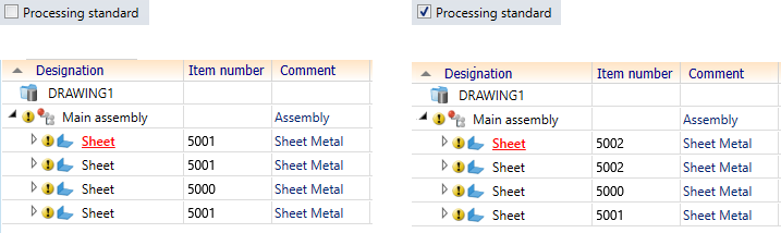
If the checkbox Processing standard is inactive, then the sheets (1), (2) and (4) are considered identical. If the checkbox is active, then only sheet (1) and (2) are considered identical.
Example - Variable through holes
Let us look at the example displayed below. There, the part is present four times in the drawing. In all four parts, a variable through hole was inserted which goes all the way through the part. Parts (1) and (3) were drilled from the top to the bottom, parts (2) and (4) were drilled the other way around. The base point is always the centroid of the entry surface. In (1) and (2) the bore is accurately displayed, in (3) and (4) only the axes are displayed.
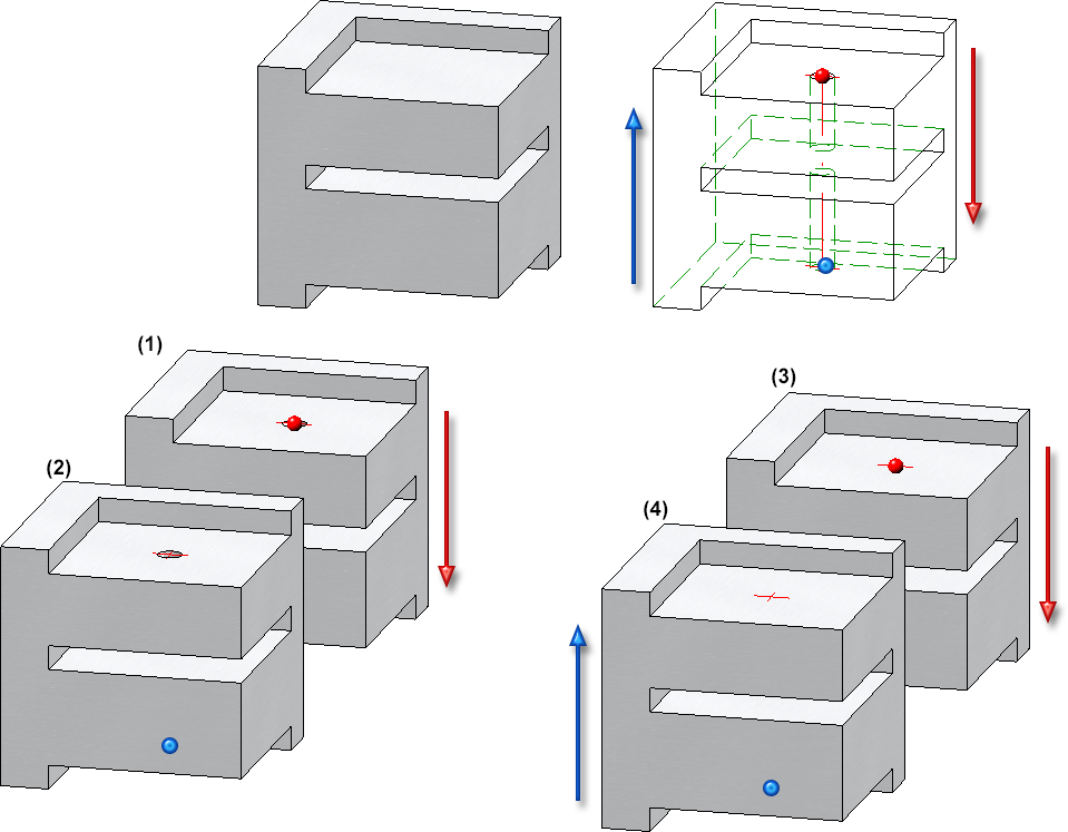
If the itemisation is now carried out, then parts (1) and (2) will be considered to be equal despite the different hole directions. The same applies to parts (3) and (4). Parts (3) and (4) therefore have a different item number than (1) and (2) because only the axes of the bore are displayed here.
Further notes
Itemisation - BOM-relevance of itemised parts
If the BOM-relevance of already itemised parts is removed, their item number is not removed but only invalidated. This is marked accordingly in the ICN (either with an asterisk * or with strikethrough numbers - depending on the selected ICN structure display), provided that in the Configuration Editor at System settings > Itemisation > Updating the parameter Set change mark when changing parts is set to Yes. However, the other item data such as the item text are not retained. If the part is later assigned BOM relevance, the "old" item number is restored during automatic positioning, provided the checkbox Preserve existing numbers where possible is active in the itemisation settings. For the item text, on the other hand, the current settings are used and not those that were active when the BOM relevance was removed.
A practical use case:
In practice, it sometimes happens that parts lists are only created for a certain quantity of parts. To do this, you can remove the BOM relevance of the unwanted parts, create the BOM and then reassign the BOM relevance. Then start the automatic positioning again (with active checkbox Preserve existing numbers where possible).
Example:
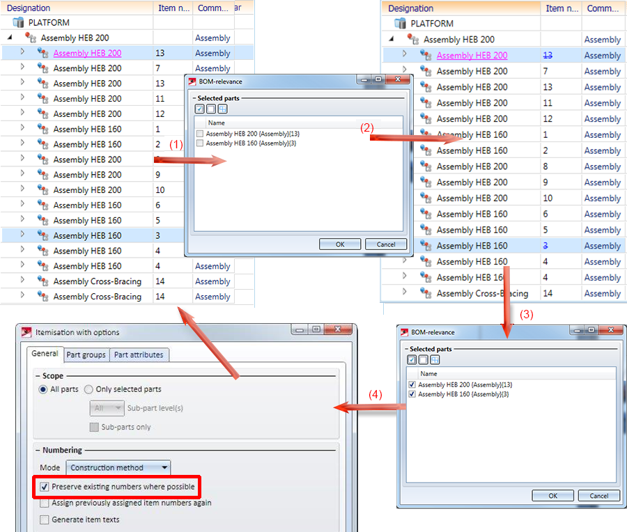
(1) Original model drawing, (2) Remove the BOM relevance for the parts with item numbers 13 and 3. The item numbers 13 and 3 are therefore invalid. (3) BOM relevance is set again. (4) The new positioning restores the invalid position numbers.
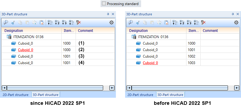
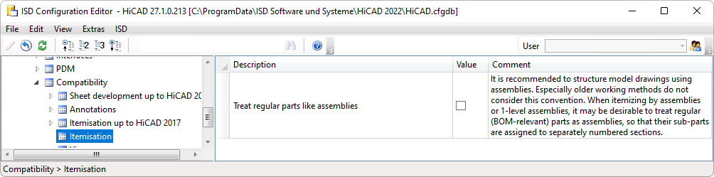
Treat regular parts like assemblies
To create a clear and efficient drawing, assemblies should be used for structuring. However, this is often not taken into account, especially in "older" ways of working. Here it can sometimes be desirable to treat regular (BOM-relevant) parts like assemblies during the itemisation, so that their sub-parts become separately numbered sections. For these cases, the checkbox Treat regular parts like assemblies is available as of SP1 in the Configuration Editor under Compatibility > Itemisation.
If the checkbox is active, regular (BOM-relevant) parts will be treated like assemblies during the itemisation in HiCAD and their sub-parts will become separately numbered sections. The prerequisite is that you have selected the mode by assemblies or - if a main assembly exists - by top level assemblies in the itemisation settings on the General tab.
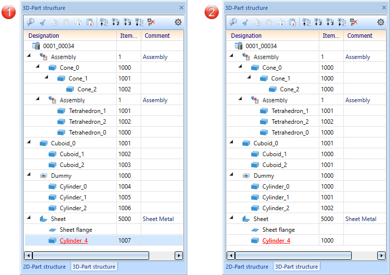
(1) Do not treat regular BOM-relevant parts like assemblies, (2) Treat regular BOM-relevant parts like assemblies
