Spread Isometry over Several Sheets
Isometry + Pipe spool drawing > Settings
General
Isometries containing representations of entire pipelines or pipeline details can now be divided into two or more partial isometries. For each of these partial isometries an own drawing sheet will be created.
 Please note:
- Isometries can not be divided in the layout plan, but only in the isometric drawing. However, the division can be revoked in the layout plan.
- You can pre-set the position of certain elements in the drawing frame, e.g. North arrow, Tripod or various List types. To do this, call the Isometry Settings function and select in the dialogue window the 2-D Drawing elements tab. Furthermore, you can also add and position arbitrary other 2-D elements existing as FGA files.
- The functions are not available for pipe spool drawings.

Specify division
Isometry + Pipe spool drawing > Settings > Specify division 
Use the Specify division function to break up an isometry drawing that shows a complete pipeline or only part of it into two or more partial isometries.
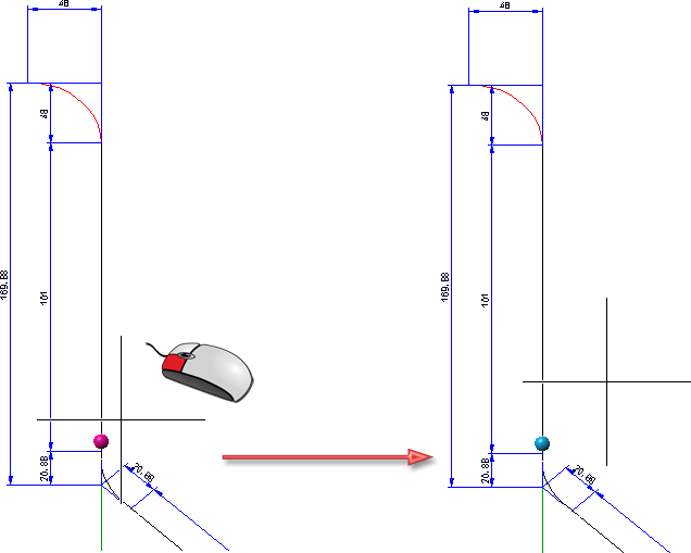
When you move the cursor over the isometry, possible division points will be marked in a different colour (Marking colour 1). Left-click to accept a marked point as a division point. When you move the cursor away from the division point, its colour will change (Marking colour 3).
If the isometry has already been subdivided into several drawings, the corresponding division points will be highlighted (Marking colour 3) as soon as the cursor is close enough to the pipeline to be processed.
-
If an already selected division point is selected again, the related division will be removed.
-
Right-click or press ESC to cancel the function without applying the selected division points.
-
Press the middle mouse button to apply the selected division points and end the function.
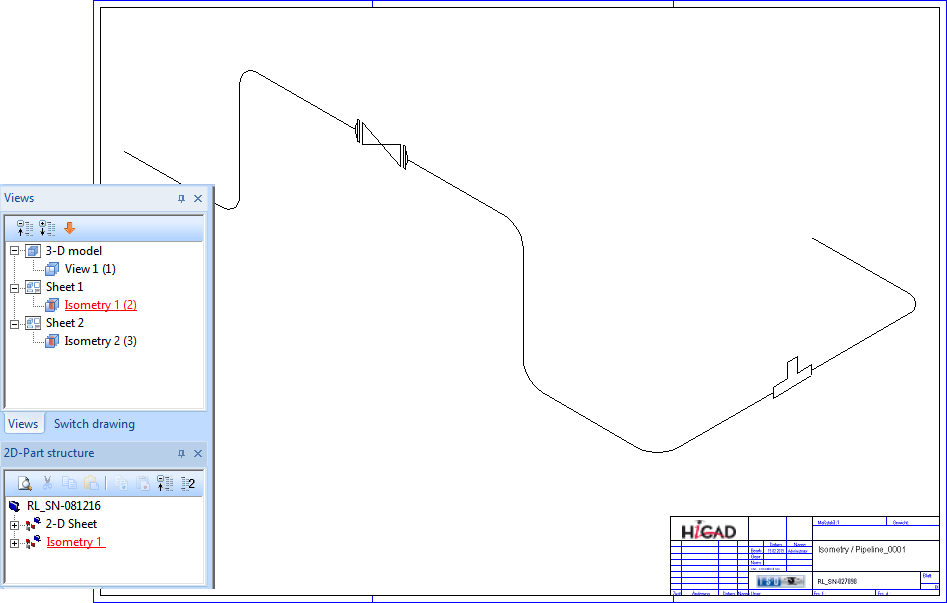
When re-generating the isometry with the function Isometry+Pipe Spool Drawing > Create > New, it will be divided according to the specified division points. The original isometric drawing will be retained.
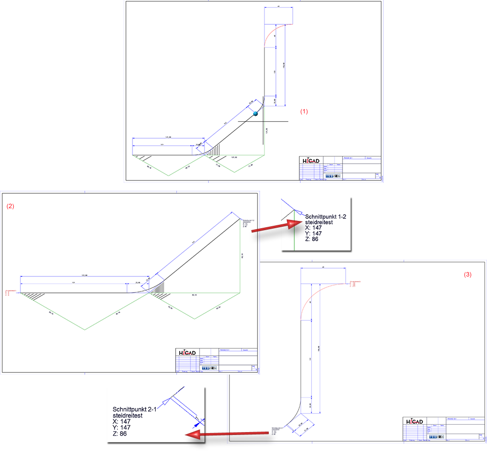
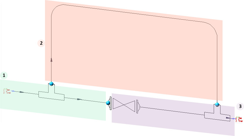
(1) Original isometry with division point, (2) and (3) Divided isometries with alternating auto-generated references
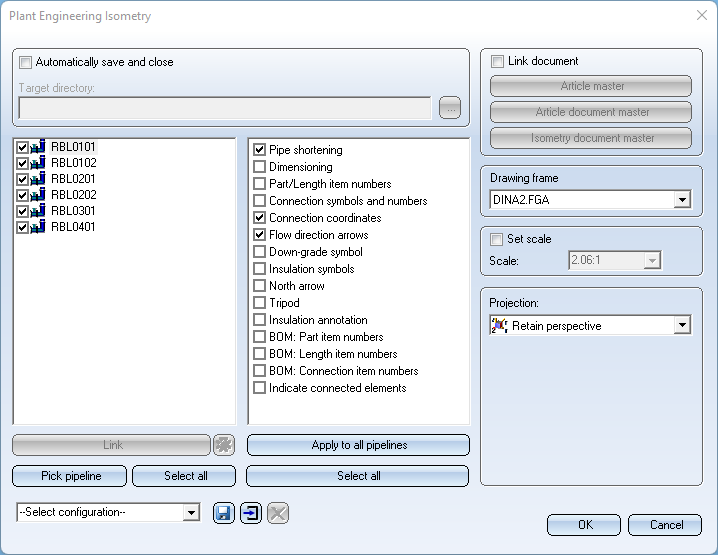
If you want to re-generate a pipeline isometry spread over two or several sheets, the spreading will be shown in a dialogue box when you call the function again (out of the layout plan). You can now select either the entire pipeline isometries, but also individual sheets for the re-generation.
![]() Please note:
Please note:
- Only one drawing will be created for each pipeline. If a pipeline isometry is subdivided, the old isometries will be deleted, and the partial isometries will be created in the same drawing. In the process, the symbols of the isometries will be arranged into assemblies and one sheet will be created for each part isometry.
Example:
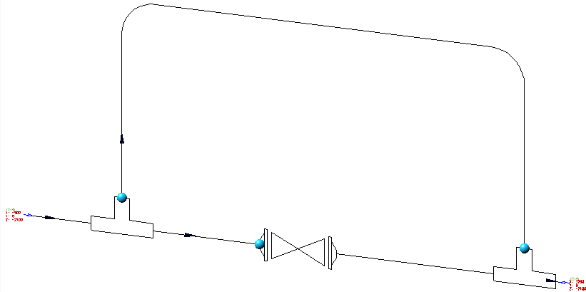
Take a look at the layout plan and its corresponding isometry shown below:
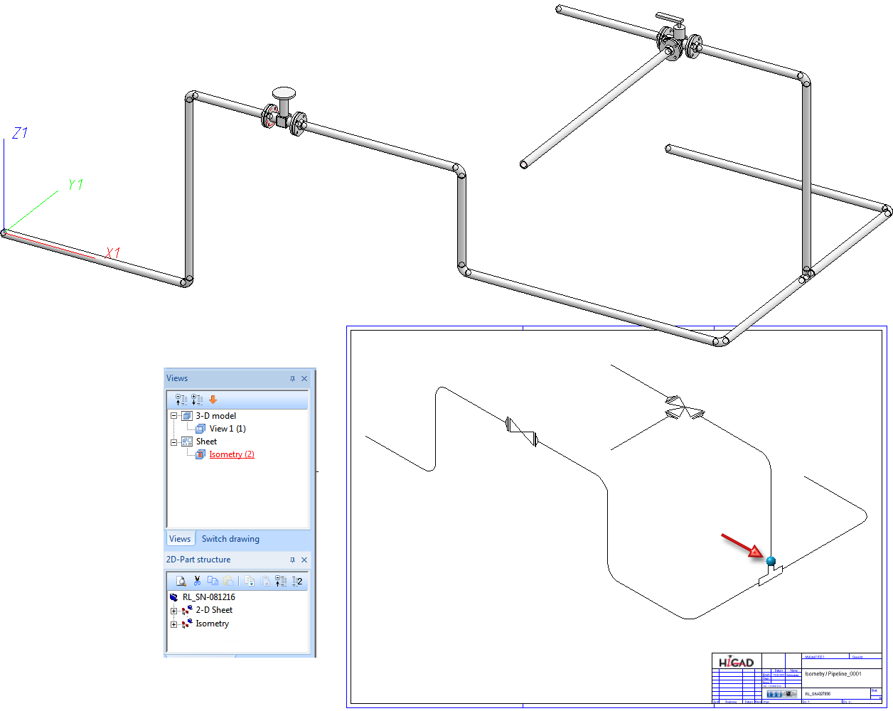
If you divide the isometry at the blue point (see red arrow) and then generate it again, the sheet with the current isometry will be deleted, and two new sheets for the partial isometries will be generated.
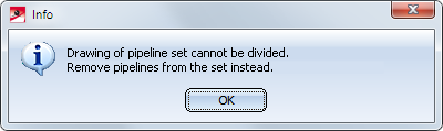
- It is not possible to spread isometries over several pages subsequently. If you try to do this, the following message will be displayed:
Annotating division points
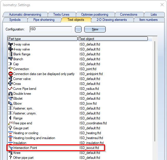
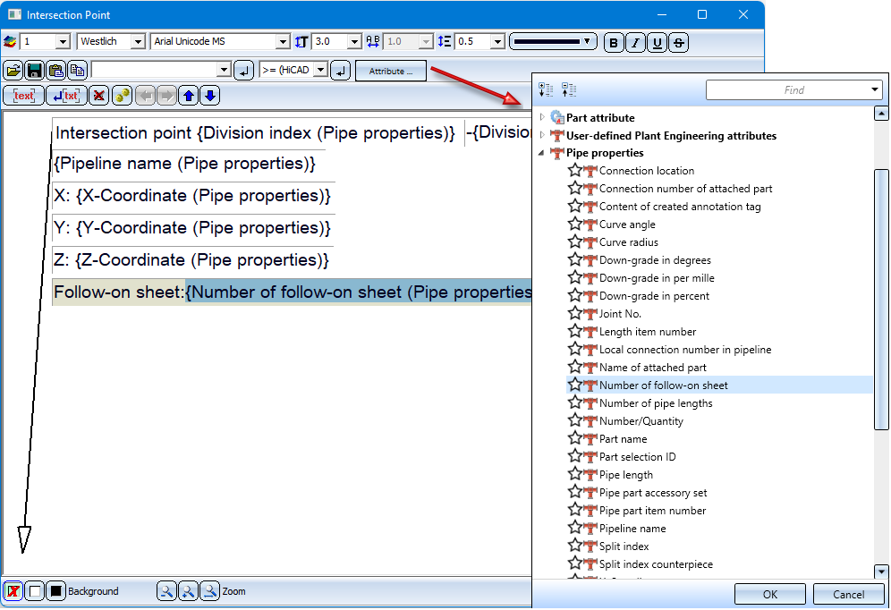
For annotating the intersections (i.e. the division points in the isometry) there is a special text object type ISD_ISOCUT.FTD, which can be configured in the isometry settings like the other text object types. In this way, the annotations are generated automatically when the isometry is created.
Useful as annotations are for example
- the coordinates (attribute %PIPE_X_COOR) or
- the division index (attribute %PIPE_ISOSPLIT_IDX).
The division index can be used to directly read where the isometric drawing is continued. However, the division index has no direct reference to the sheet number. Especially when there are many subdivisions, finding the next partial drawing can sometimes be rather difficult.
As of HiCAD 2022 SP2, the output of the Number of follow-on sheet (attribute %ISO_CONTINUED_ON) is useful here. This attribute refers directly to the sheet on which the isometric drawing is continued.
For annotating the intersections (i.e. the separation points in the isometry) there is a special text object type ISD_ISOCUT.FTD, which can be configured in the isometry settings like the other text object types. In this way, the annotations are generated automatically when the isometry is created.
To make it even easier to follow the sequence of the sheets containing the partial drawings, HiCAD additionally takes into account the flow at the division points and thus determines the sequence of the sheets.
Generally, the longest path between the sections that follows the flow is determined. However, this only works if the flow through the sections is directed and acyclic, i.e. has no circles. Otherwise, HiCAD will arbitrarily determine the sequence of the sheets as before.
Example:
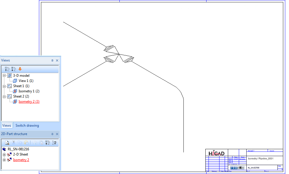
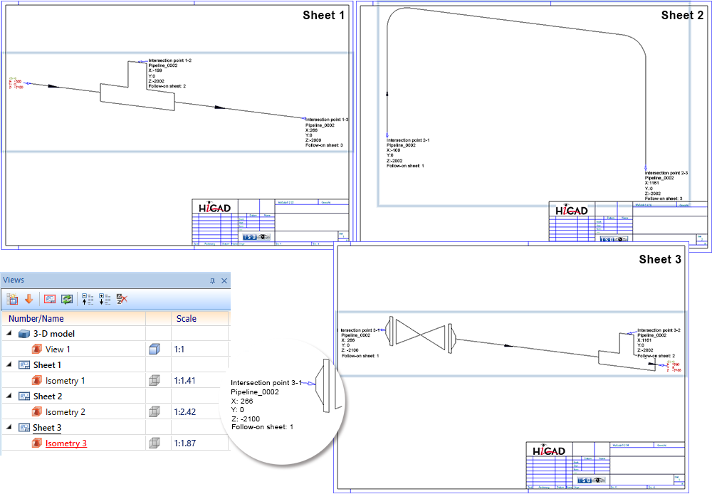
In the isometry shown below, three division points are defined and then the isometry is recreated for the three resulting sections.
The sequence of the sheets is based on the flow between the different sections.
Generally, the longest path between the sections is determined that follows the flow. However, this only works if the flow through the sections is directed and acyclic, i.e. has no circles. Otherwise, the leaf sequence is determined arbitrarily by HiCAD. In the above example, however, the flow meets the requirements and the result then looks as follows:
The number of the follow-on sheet (attribute %ISO_CONTINUED_ON) is not preset on the ISD side in the file the ISD_ISOCUT.FTD. If the attribute is to be output in the partial drawings of the isometry, you must adjust the FTD file manually.
Undo division
Isometry + Pipe spool drawing > Settings > Undo division 
Plant Engineering > Isometry / Pipe Spool Drawing > Settings > Undo division
Load the isometric drawing in which you have specified one or several division points. To undo the division and spreading over several sheets, proceed as follows: If you have already specified the division points in the layout plan, load it.
Now call the Undo division function.
When you now re-generate the isometry, the division and spreading of the drawing over several sheets will be undone.
Warning if isometry division becomes invalid
If the pipeline from which the isometry was generated is contained in the isometry as a referenced part (see Reference Isometries and Manage via Database), it is possible that the pipeline will be processed further after division of the isometry: Further parts might be added, or existing parts might be replaced with other parts. These parts are initially not assigned to any of the split isometries.
Before re-generating the isometry from the layout plan, HiCAD therefore checks whether there are any parts which are not assigned to any split isometry yet.
Possible are two cases:
- The assignment can take place automatically via the adjacent parts.
In this case the user will be asked whether HiCAD should execute the automatic assignment.
- The adjacent parts do not allow an unambiguous assignment, as they had been assigned to different split isometries.
In this case HiCAD asks if you want to fully reset the isometry division.
In both cases the previously unassigned parts will be highlighted in the layout plan.
Example of Case 1
The division (Isometry 1 and 2) takes place at the connecting point in the red circle. The right pipe (3) was added after the isometry division.
After confirming with Yes:
Example of Case 2
The division (Isometry 1 and 2) takes place at the connecting point in the red circle. The middle pipe was removed and replaced with an new pipe (3).
After confirming:

Generate Isometry/Pipe Spool Drawing (PE/Iso) • Isometry and Pipe Spool Drawing (PE/Iso) • Isometry and Pipe Spool Drawing Functions for the Layout Plan