Pipe Parts: Elbows
Plant Engineering > New > PipePrt > Pipe parts > Elbow
When fitting elbows you have the following options:
 In the straight sections of elbows, branches can be created with the help of saddle connections or pipes with smaller diameters. Click here for further information.
Set individually
Plant Engineering > New > Pipe parts > Elbow > Set individually 
Here we will describe the insertion of an elbow with the following settings:

|
Pre-set minimum pipe length: 10.00 |
|
|
Pre-set maximum pipe length: 6000.00 |
|
|
Auto-fit connection parts |

|
Include accessory sets |
|
|
AutoFlange for Part exchange |
|
|
AutoFlange for Part insertion |
- In the selection window, choose the part type Elbow.
- Select the insertion type Set individually.
- Select the corner of the guideline on which you want to place the elbow.
- Select, depending on the current Part selection settings, the desired elbow via part search in HELiOS, or part search in the HiCAD catalogue.
- Close the dialogue window.
HiCAD places the elbow at the required position.
The guideline is processed as follows:
- HiCAD replaces the selected corner by a curved edge with a suitable radius and length. The new edge is set on Layer 0, i.e. it is only visible when the layer is active. Edges that previously converged at the corner are appropriately shortened.
- You can now either insert an elbow on the next corner or select the MMB to cancel the option.
- If you select another corner, HiCAD asks if you want to insert an identical part, if you respond with yes, part selection is unnecessary.
In guideline mode, angles are dealt with as follows:
Irrespective of the angle on the identified guideline corner, the part search in the database initially looks for a 90° pipe bend. The Standard designation, Nominal diameter, Bend angle and Wall thickness are then detected and used as search criteria for the selected part. If you are allowed to cut the part to fit the angle, HiCAD finds the elbow with the next largest existing angle. Let us assume that bend angles of 45°, 90° and 180° exist for a part standard, and that the edges on a guideline build the angle of 34,5° required by for the elbow, HiCAD automatically selects the 45° bend and cuts it to fit the required angle.

Set all
Plant Engineering > New > Pipe parts > Elbow > Set all 
This option enables you to set a selected elbow on all guideline corners of the active pipeline. The angle of the elbow is automatically adjusted to the angle of the guide-line corner. Corners that are already occupied by elbows are not changed. Proceed as follows:
- In the selection window, choose the part type Elbow.
- Select the insertion type Set all.
- Select, depending on the current Part selection settings, the desired elbow via part search in HELiOS, or part search in the HiCAD catalogue.
- Select a part from the list.
The angle selected does not influence the actual angle of the elbow. Only 180° bends are offered, which can be cut to fit any smaller angles. The appropriate search criteria are automatically set (Attribute Angle (=180) and Attribute beliebig_teilbar* = „1 = yes“) = (arbitrarily_divisible*).
All corners are then automatically processed as described for the Set individually option.
180° bend
Plant Engineering > Pipe parts> Elbow > 180° bend 
Use this function to place a 180° pipe bend on a particular corner of the guideline. Proceed as follows:
- In the selection window, choose the part type Elbow.
- Select the insertion type 180° bend.
- Select, depending on the current Part selection settings, the desired elbow via part search in HELiOS, or part search in the HiCAD catalogue.
- Close the dialogue window.
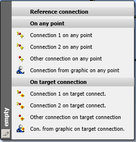
- The elbow is now attached to the cursor. Identify the corner of the guideline onto which you want to place the elbow. Alternatively,you can right-click and activate the Reference connection context menu in order to determine a new connecting point.
- After specifying the insertion point, the Rotation angle dialogue window will be displayed. Rotate the part into the required position.
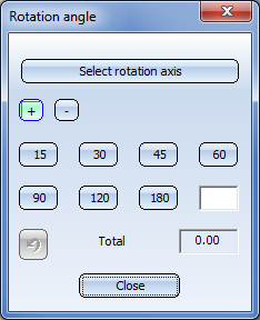
You can now either select End to exit the function, or Continue to insert the same part again.
Adjust to displacement
Up to HiCAD 2021 this type of insertion could be used for the following (or similar) situations:
- The straight pipe runs in Y-direction, the vessel stands perpendicular on the XY-plane.
- Now you want to move the vessel slightly in X-direction.

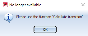
As of HiCAD 2021 SP1, the Calculate transition  function must be used in such cases.
Please note:
The parts and insertion types provided by the Pipe parts function are defined in the file rohrbt_list2.dat in the HiCAD sub-directory makroanl. If you have adjusted this file manually, then the insertion type "Adjust to displacement" may still be available after an update installation. In this case, the following message is output when this insertion type is selected.

Pipe Parts (PE) • Part Selection - Catalogue or Database (PE) • General Information on Pipe Parts (PE)