Chamfer Edges and Surfaces
3-D Standard > Process > Chamfer 

Element selection
After calling the function, select the elements to be chamfered in your drawing, i.e. the edges and/or surfaces to be chamfered.
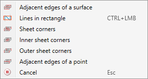
With a right-click you can activate a context menu with further selection options of the elements to be chamfered:
|
Adjacent edges of a surface |
All edges that are adjacent to a certain surface are selected as elements to be chamfered, i.e. all edges perpendicular to this surface. Select the desired surface.
|
|
Lines in rectangle |
All edges that lie within a rectangle will be selected. Hold down the left mouse button and draw the rectangle.
All edges that are completely inside the rectangle will be selected as elements to be chamfered. Note that only edges will be selected here. |
|
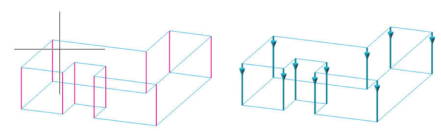
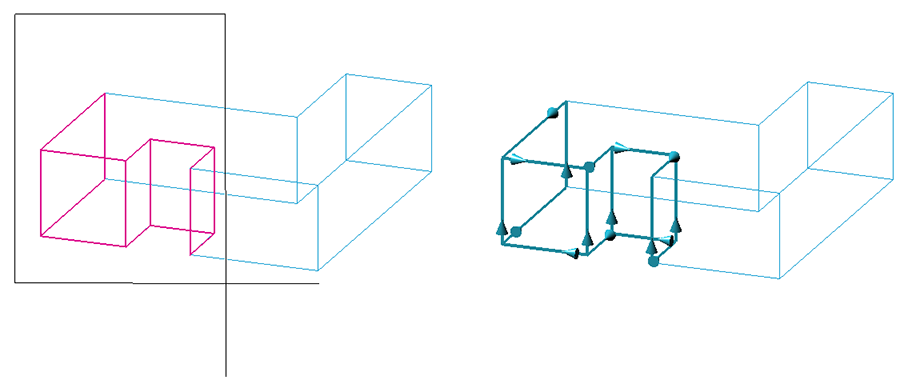
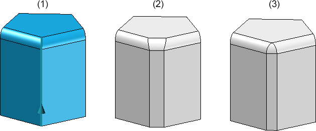
Sheet corners |
This option allows you to select all corners, all inner corners or all outer corners of a sheet metal part in one step. All vertical edges, inner or outer edges in sheet thickness direction are selected as elements to be chamfered. Note that corners are only taken into account if no flanges are attached to the corresponding edge. The elements can be chosen from different elements of sheet metal parts.
(1) Outer corners, (2) Inner corners, (3) Corners |
|
Inner sheet corners |
|
|
Outer sheet corners |
|
|
Adjacent edges of a point |
This option allows you to select all edges adjacent to a point in one step.
|
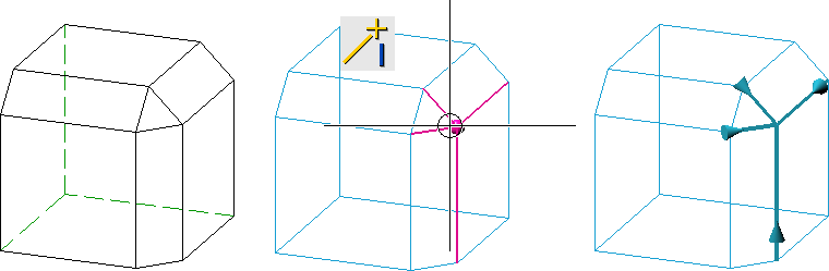
For edges, the edge direction is visualised after selection. This depends on the cursor setting during selection. Please note that the edge direction is taken into account for variable chamfering and chamfering of segments.
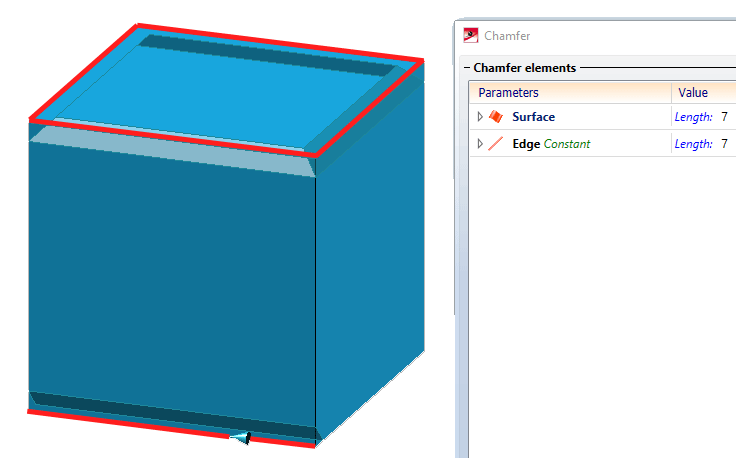
List of elements to be chamfered
All elements selected for chamfering are entered into the list of chamfer elements in the dialogue window.
Each element in the list has several rows, the number of which depends on the selected chamfering parameters. The entries have a tree-like structure and are assigned to the respective element in the list as sub-entries.
- The first row of an entry is always the element type, which is indicated by a corresponding symbol.
 Edge
Edge
 Surface
- For edges, the chamfer type is displayed next to the element type - constant or variable.
- If you want to check which edge/surface of the drawing belongs to an entry in the object list, simply click with on the line containing the element type. The corresponding edge/surface will then be highlighted in the drawing. Multiple selection is also possible.
- If you select an edge or surface in the drawing that is already contained in the list of chamfer elements, then the entry will be removed from the list.
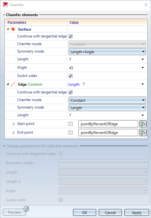
Chamfering parameters
The rows subordinate to the element type contain the chamfering parameters selected for the respective element.
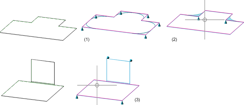
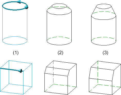
Continue with tangential edge
If you want all tangential edges to be automatically chamfered when chamfering one edge, activate the Continue with tangential edge checkbox.
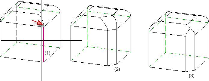
(1) Selected edge with tangential edge, (2) chamfer without tangential continuation, (3) chamfer with tangential continuation
A tangential continuation is also possible for edges in flanges and bend zones of sheet metal parts.
Symmetry mode
|
Length |
This input type executes chamfering symmetrically, i.e. the distance between the chamfer cross-section and the chamfer edges is the same on both sides.
Left: Original part with selected edge; Right: Chamfered edge, input type: Length Enter the value for the length.
|
|
Length + Angle |
Here you chamfer the edges by specifying the chamfer length and the chamfer angle. Enter the desired values. You can use the Switch sides checkbox to define to which side of the selected edge the chamfer length will be applied.
Left: Selected edge, Centre: Chamfered edge, input type: Length and Angle, Switch angle no, Right: Switch angle yes.
|
|
2 lengths |
Here, you chamfer the edges/surfaces by specifying two chamfer lengths. This means that asymmetrical chamfers are also possible, i.e. the distance between the chamfer cross-section and the chamfer edges is different on both sides. Use the Switch sides checkbox to define to which side of the selected edge the specified chamfer lengths will be applied.
(1) Selected edge, (2) Input type: 2 lengths, both 20 (symmetrical), (3) 2 lengths, 20 - 40 (asymmetrical)
|
|
Rolling ball |
Here, the Rolling ball algorithm is used to create the chamfer. To do this, enter the radius of the "rolling ball". This process will lead to the boundary curves of the chamfer being created by touching the "rolling ball". The Rolling ball option is used if you want to create tapered chamfers.
(1) Original and selected edge, (2) Chamfer with length, (3) Chamfer with Rolling Ball |
Chamfer mode
For edges, two different chamfer modes are available - constant or variable. For surfaces, variable chamfering is not possible.
| Constant |
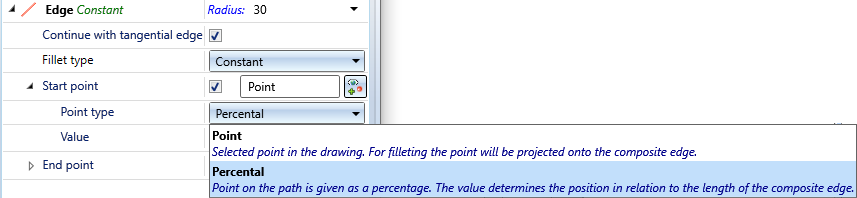
When selecting constant chamfering, the chamfer length is the same at all points of the edge to be chamfered. If you only want to chamfer a segment of the edge, rather than the entire edge, you can define this segment by activating the Start point and/or End point checkboxes. These points can be defined with a point option or by specifying a percentage value related to the edge length. Please note that the start point (in relation to the direction) must be located in front of the end point!
|
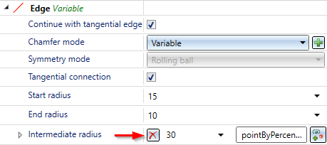
| Variable |
Variable chamfering is always executed with the Rolling ball symmetry mode. Here you can select different radii for the rolling ball at the start and end points of the selected edges and at any other intermediate points. The variable chamfering can be created with a Tangential connection. If the checkbox is active, the chamfer will be created with a gradual transition between the points. The transition is tangential. Deactivate the checkbox to create chamfers with linear transitions between the points. Enter the radius of the rolling ball at the start and end point of the edge. To insert radii at intermediate points, click on the
(1) Selected edge, (2) Different start and end radius with tangential connection, (3) Different start and end radius with linear transition, (4) Different start, end and intermediate radius with tangential connection As with constant chamfering, chamfering of segments is also possible here. The initial radius is the radius at the start point. |
 symbol and determine the point in your drawing. This point does not have to be on the selected edge but it will automatically be projected onto the selected edge.
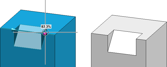
 symbol and enter the value for the intermediate radius.
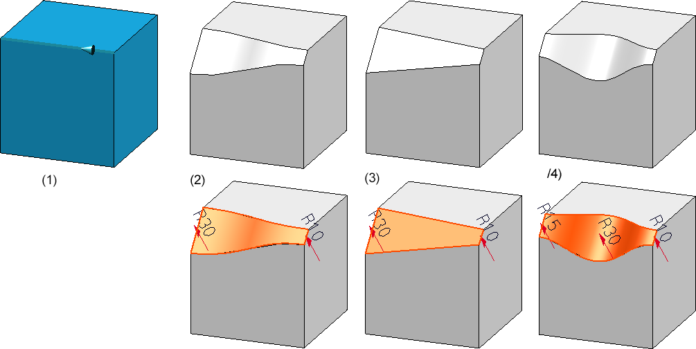
Change parameters for selected elements
Certain parameters can be changed in one step for several chamfered elements. These are:
- the symmetry mode,
- the chamfer lengths and the chamfer angle (depending on the symmetry mode)
- the tangential continuation of edges and
- the switching.
To do this, select the desired chamfer elements in the list. As usual in Windows, the CTRL and SHIFT keys are allowed.
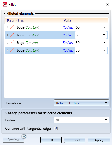
If you have selected elements with different chamfer or symmetry modes, the text <Different values> will be displayed as a note under the parameters in the input fields. All selected elements are chamfered with the values specified under Change parameters for selected elements when clicking the OK button.
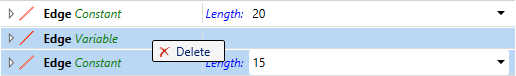
Deleting entries from the element list
You delete entries from the element list by right-clicking on the corresponding line and then selecting the Delete function. The usual Windows multiple selection is also possible.
Entries for intermediate radii during variable chamfering can be removed by clicking on the  symbol.
If you select an edge or surface in the drawing that is already included in the list of chamfered elements, the entry is removed from the list!

The 'Chamfer' Dialogue Window (3-D) • Fillet + Chamfer (3-D) • Model and Process Parts (3-D)