Views > New > Detail  > Detail view Cuboid/Sphere
Use this function to define detail views. Here the detail is not determined by a sketch but by defining a cuboid or a sphere.
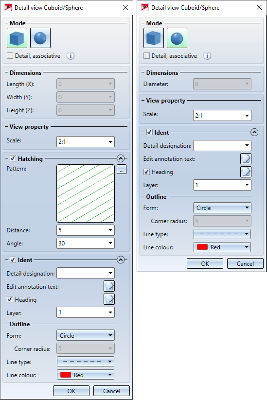
You can switch between both modes in the Detail view dialogue window.
Note:
If you right-click in the input field for the scale, the function Add scale is available. With this function you can define further individual scales for the current model drawing without having to leave the scale function. The predefined scale lists can be edited and additional scale lists can be defined. How this works is explained in the Manage Drawing Scales paragraph. To learn how to create drawing-independent scale lists, see the Create and Edit Scale Lists topic.
![]() Please note:
Please note:
-
The suggested scale is determined by the scale of the original view and the setting in the Configuration Editor at System settings > Visualization > Views > Scale for new detail views:
- Like original view or
- Next higher scale.
-
The detail view is linked to the original view.
-
For the detail view, the projection of the original view is used.
- To change the detail view Cuboid / Sphere select the Change detail view
 function in the Views Ribbon or in the context menu for views. Afterwards the corresponding dialogue window is displayed.

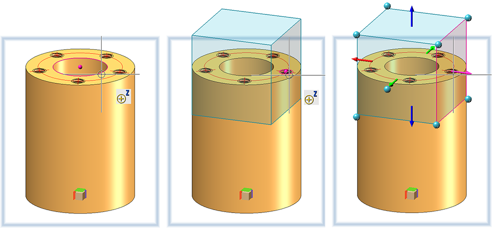
Detail view Cuboid
- Determine the centroid of the cuboid in the drawing. Then you can simply draw the cuboid dynamically by moving the cursor. A preview of the cuboid will be displayed. When you drop the cursor (also with the help of a point option), direction arrows are shown. Afterwards you can still change the size of the cuboid. To do so, either enter the desired dimensions in the dialogue window or select an area of the box in the preview and drag the area in the desired direction. In addition, you can also drag the point symbols
 . This way you can also use point options of the Autopilot and the Point options menu.
-
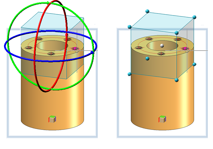
In addition to scaling, i.e. dragging the individual side surfaces, you also have the option of rotating or moving the cuboid. The corresponding functions are available in the context menu after pressing the right mouse button. If Rotate is selected, the cuboid can be rotated around an axis by selecting the rotation circle of the respective axis with the cursor and then dynamically rotating it with the cursor. When moving, select one of the marked points on the cuboid and drag the point to the new position.
- Select the scale for the detail view, e.g. 2:1.
- If you want to hatch the cut surfaces, activate the Hatching checkbox. Select the hatching distance, the hatching angle and the hatching pattern.
- In the Identarea you define how the detail section is to be identified and annotated in the original view and you determine the caption for the detail view. If you do not want an annotation, deactivate the checkbox. The operation of the area is analogous to the definition of detail views.
- Close the dialogue window with OK or press the middle mouse button.
- Then determine the position of the detail view.
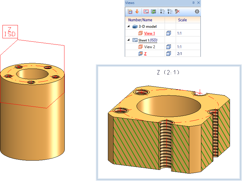
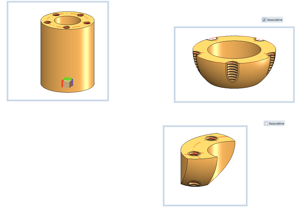
Example of a Detail view Cuboid with identification and annotation of the original view (detail identification and sheet name, exact detail section) as well as caption in the detail view.
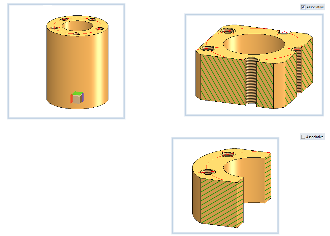
Associative behaviour
If one or more HiCAD Point options are used to define the box, the checkbox Detail, associative can be used to define how the detail view should behave if the corresponding points are moved due to changes in the drawing, as is the case in the Detail view cuboid mode.
If the checkbox is active, the detail follows the changes, it can, for example, "go along" with a moved geometry.
This is not the case if the checkbox is inactive (default setting). The detail view always shows the same spatial section, regardless of whether the original geometry is still at this position.
An example:
Let's look again at the example shown above. As a reminder: We had placed the centre of the detail cuboid in the middle of the top of the cylinder with the Point option Z. Now we move the cylinder to the right.
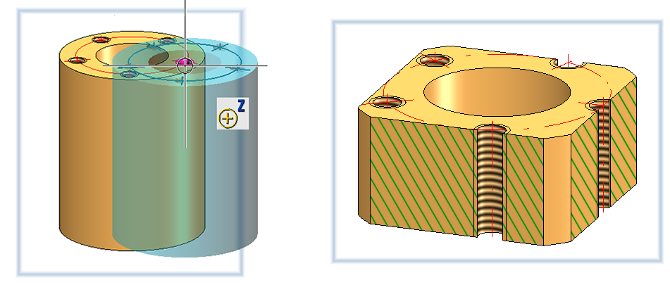
The following image shows the difference between associative and non-associative behaviour after updating the detail view.
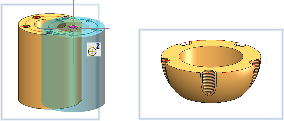
Detail view Sphere
- Determine the center of the sphere in the drawing. Then you can simply draw the sphere dynamically by moving the cursor. A preview of the sphere is displayed. To change the size of the sphere, either enter the desired diameter in the dialogue window or select the sphere in the preview and change the size dynamically with the cursor. If you want to move the sphere, click on the centre point and drag the sphere to the desired position.
- Select the scale for the detail view.
- In the Identarea you define how the detail section is to be identified and annotated in the original view and you determine the caption for the detail view. If you do not want an annotation, deactivate the checkbox. The operation of the area is analogous to the definition of detail views.
- Close the dialogue window with OK or press the middle mouse button.
- Then determine the position of the detail view.
Associative behaviour
If a HiCAD Point option is used to determine the centre of the sphere or the size of the sphere, then, as in the Detail view, Cuboid mode, the checkbox Detail, associative can be used to define how the detailed view should behave if the corresponding points are moved in the original view.
If the checkbox is active, the detail follows the changes, it can, for example, "go along" with a moved geometry.
This is not the case if the checkbox is inactive (default setting). The detail view always shows the same spatial section, regardless of whether the original geometry is still at this position.
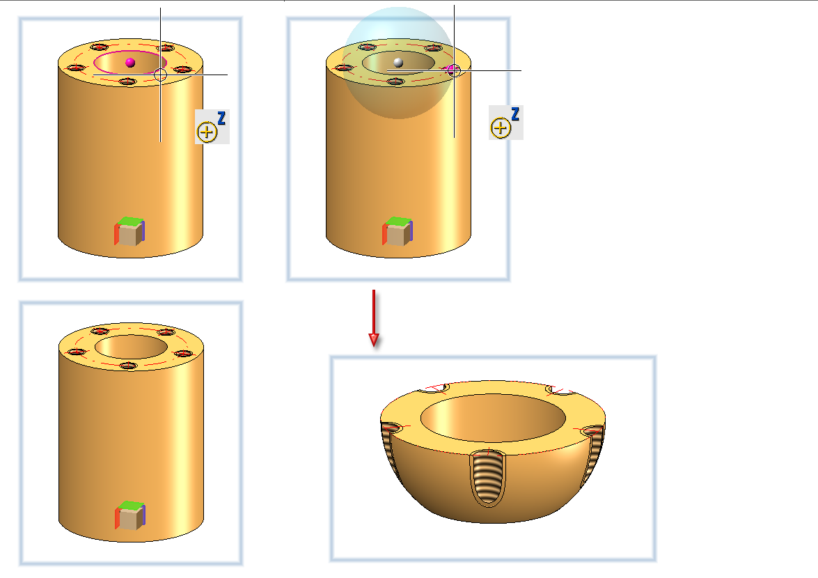
An example:
Let's look again at the example shown above. As a reminder: We had placed the centre of the detail cuboid in the middle of the top of the cylinder with the Point option Z. Now we move the cylinder to the right.
The following image shows the difference between associative and non-associative behaviour after updating the detail view.