
Automatic annotation
The automatic annotating of grid subsystems is only possible for derived drawings.
An annotation of the grid sub-system will only be created if:
- system axis annotations are created (can be set in the Drawing derivation dialogue or Configuration Editor, respectively)
- an edge of the grid runs parallel to the beam axis
- the grid edge is located in the vicinity of the beam (can be set in the Drawing derivation dialogue or Configuration Editor, respectively)
- the sub-system is already connected to the found grid edge, i.e. the sub-system edge intersects or converges with the grid edge.
Display of sub-system annotation
Representation of the sub-system annotation
If the sub-system line is located in the screen plane of the view, the sub-system annotation represents a detail of this line. The connecting point of the sub-system on the grid is indicated by a symbol (can be set in the Configuration Editor).
If the sub-system line is not located in the screen plane of the view, the sub-system annotation will be represented as a vertical line. The connecting point of the sub-system on the grid is indicated by a symbol (can be set in the Configuration Editor).
Left: Model drawing with grid and grid sub-system; Right: Detail of workshop drawing
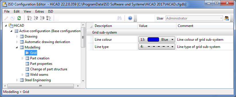
 The automatic annotation settings for derived drawings can be specified in the Configuration Editor at Automatic drawing derivation > Production drawing > Grid annotation.
Manual annotation
3-D Dimensioning + Text > Symbols > Grid Annotation 
Grid subsystems can also be annotated manually. To do this, use the Grid annotation, Individual function.
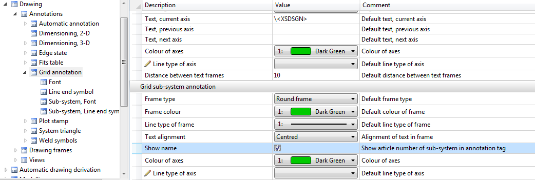
After calling the function, select the edge of the grid sub-system. The annotation will be created immediately. The settings specified at Drawing > Annotations > Grid annotation will be considered for its representation.
Please note:
- The article number of the grid sub-system will only be written into the text box of the annotation tag, if in the Configuration Editor, at Drawing > Annotations > Grid annotation, the Show name checkbox has been activated.
- When annotating the sub-systems manually, a designating of connecting points with symbols is not possible.
- If you choose a different edge or two points instead of the edge of a grid sub-system, an annotation tag of the grid plane will be created.
Edit annotations of grid sub-systems
Use the functions of the context menu to edit and move the annotations. You open the context menu with a right-click on an annotation:
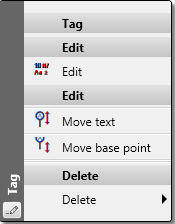
Edit
Use this function to change the representation of annotation tag in grid-subsystems. When you call the function, the following dialogue window will be displayed:
The setting options in the dialogue window correspond to the same-named parameters in the Configuration Editor.
The settings beneath Symbol only apply to automatically created annotations!
Move text/base points
Use these functions to move the text box or the base point of an annotation tag, respectively. After calling the function the text box/the base point will be attached to the cursor; you can then choose a new position.
A moving to the line start/end via Drag & Drop is also possible.
Delete
Use the functions of the Delete sub-menu to delete annotations of grid sub-systems:
- Individual,
- Only active part,
- Active view,
- Entire drawing.
