Create Grid Annotation
3-D Dimensioning + Text > Symbols > Grid... 
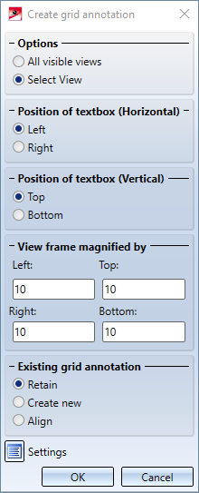
Use this function to individually annotate the axes of a 3-D grid (system axes). When you call the function, the Create grid annotation window will be displayed.

Options
- Selection
By activating the corresponding radio button you specify whether only the system axes of a particular view, or the system axes of all visible views are to be annotated. If the Select view checkbox is active, HiCAD will prompt you, after exiting the dialogue window with OK, to identify the desired view. - Position of textbox
These options enable you to specify the horizontal (left/right) and the vertical (top/bottom) position of the annotation text.
- View frame magnified by
The length of the annotation lines will initially be determined by the bounding box (1) embracing all parts of the drawing. In addition, you can enter in the fields below View frame magnified by a value (2), by which the annotation lines are to be lengthened or shortened (negative value) at the top, bottom, left and right.
- Existing grid annotation
Here you specify how to handle existing grid annotations. - Retain
Existing grid annotations will not be changed. - Create new
Existing grid annotations are deleted and created anew, according to the current settings. - Align
Existing settings are realigned according to the current settings. Alternatively, you can also use the Align grid function for this.
Settings
Click the Settings  icon in the Create grid annotation to specify the settings for the grid annotation, e.g. the text, the representation of the symbol frame, the colour and the type of the annotation lines, font, font size, text colour etc.
The System axis annotation dialogue window is displayed:
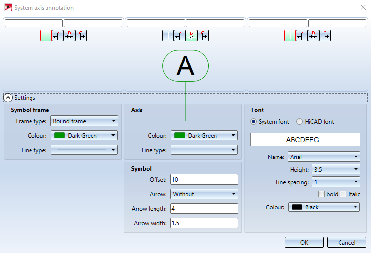
In this dialogue window you can choose the desired settings for grid annotations. in the upper part of the dialogue window you can specify the text of the axis annotation, in the lower part of the window you can define the representation of the annotation.
Define annotation text
HiCAD displays the annotation text selected for the current grid in the middle field of the dialogue, e.g.  , as a presetting for the annotation of the current system axis . If desired, you can add a prefix and postfix that you enter in the text input fields at the top.
 .
.
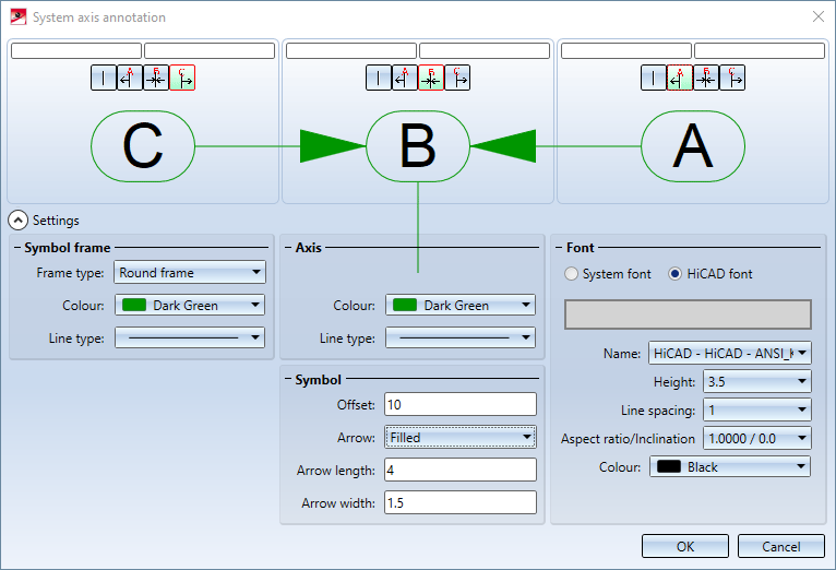
The icons have the following meaning:
|
|
No axis annotation |
|
|
The annotation text of the axis preceding the current system axis is used. If there is no preceding axis, the text remains unchanged. |
|
|
The annotation text of the current system axis is used. |
|
|
The annotation text of the axis following the current system axis. If there is no following axis, the text remains unchanged. |


If you want to display references to neighbouring axes, use the corresponding left/right area of the dialogue window:
Representation of the annotation
In the lower area of the dialogue window you specify the representation of the axis annotation. If this area is not visible, it can be displayed by a click on the  symbol.
The following setting options are available:
|
(1) Symbol frame |
|
|
|
(2) Axis |
|
|
|
(3) Symbol |
|
|
|
(4) Font |
|
![]() If you refer in a system axis annotation to the axis annotation of the 3-D grid, the system axis annotation will be adjusted if you change the axis annotation subsequently with the Grid parameters function.
If you refer in a system axis annotation to the axis annotation of the 3-D grid, the system axis annotation will be adjusted if you change the axis annotation subsequently with the Grid parameters function.
