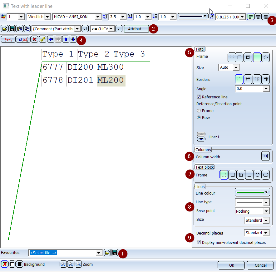
Annotation Editor
2-D Dimensioning + Text > Text > New  > Settings, Text block
2-D Dimensioning + Text > Text > New > Settings, Text with leader line 
2-D Dimensioning + Text > Text > New > Settings, Itemisation 
2-D Dimensioning + Text > Text > New > Settings, Standard designation 
You use the annotation editor to define the settings for the following annotations:
You also make changes to these annotations in the annotation editor. Furthermore, you also create text blocks and texts with leader line there.
A text block/annotation may, in turn, consist of several text blocks, which can be formatted differently. Multiple selection of text blocks is possible:
- Double left-click outside the texts: Select/deselect all
- CTRL + left-click in the text: Add to/remove from selection list
- SHIFT + left-click in the text: Add/remove all input fields in this row
- Left-click in the text: Re-set multiple selection, activates the input field that you click
- Double left-click in the text: Select word
- SHIFT + LMB: Mark texts between active field and selected field
After selecting the texts you can use the key shortcut CTRL+C to copy them to the clipboard, thus making them available to other programs (Word, Excel, etc.). You can also copy tables from Word or Excel into the Annotation Editor with CTRL+V, retaining their tabular structure.
2. Composition of the annotation
4. Insert, delete, move and display text blocks
5. Representation of outer frame and leader line
7. Representation of frame around text blocks
10. Background, Zoom, End Editor

1. Load and save settings
Annotation settings can be saved as favourites. The file format is *.FTD. In the HiCAD SYS directory you can find various .FTD files with predefined annotations.
 Use this function to save the current settings. The file format is .FTD.
 Use this function to load the annotation settings saved to a .FTD file. The settings in the file will be displayed in a preview window after loading.
2. Composition of the annotation
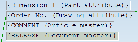
An annotation is composed of various text blocks. Each of these text blocks can consist of various text elements. These include part attributes, database attributes, drawing attributes, special characters or any alphanumerical texts. The annotation you choose is displayed in the preview window. Each text block is marked by a prominent border.
All attributes can be selected from the listbox. Each attribute is marked with a symbol indicating the attribute group. When selecting attributes, you can mark frequently used attributes as favourites for faster access. To do this, simply click on the  symbol next to the attribute name. The symbol then turns yellow
  . Attributes marked in this way are listed in the selection window under Favourites. When you move the cursor over an attribute, a tooltip will show you to which attribute group the attribute belongs:
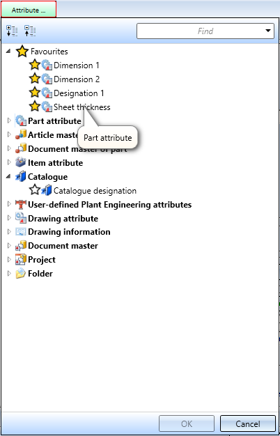
You can also use Drawing attributes within an annotation. The selection takes place via the right listbox of the Annotation Editor. If drawing attributes are changed, the annotation will be automatically adjusted accordingly.
![]() Please note:
Please note:
- The procedure for using project attributes is as follows. If the part master is assigned to a project, the project attributes of the part are used. Otherwise, project information of the model drawing is evaluated.
- Prefixing the string %DBAD for document attributes or %DBAP for project attributes - as in earlier HiCAD versions - is no longer necessary.
![]() Important:
Important:
If a model drawing contains annotations or text blocks with HELiOS attributes, these are automatically updated from SP1 when the drawing is loaded. This behaviour can be switched off in the Configuration editor. For this purpose, the checkbox Update annotation tags with HELiOS attributes is available at System settings > HELiOS.
Tables
You can use tab stops (besides the selection of HiCAD fonts) to apply a tabular alignment to text blocks of an annotation. To do this, just place the cursor at the required position of the text and press the tab stop key on your keyboard.
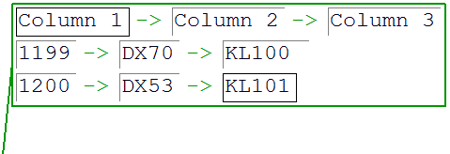
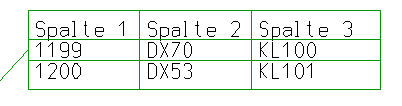
In this context please also note that you can assign horizontal and vertical dividing lines to texts which have been separated with tab stops. This allows the creation of complete tabular annotations. In the Columns area, you can set the width for each column explicitly.
Use the option at the bottom right of the dialogue to specify the number of decimal places for each numerical text block.
To assign text elements to a text block, place the cursor in the relevant text block. You can now enter texts directly via the keyboard.

Use the three icons shown above to load texts from a file, take over texts from the clipboard or copy them to the clipboard.
|
Load text from file |
Use this function to load ASCII files or formatted text (*.RTF, RichText). When loading text from RTF files you can also take over the font, as well as tab stops and indents. |
|
Save text |
Use this function to save marked text as text (*.txt) or annotation template (*dat). |
|
Insert text from clipboard |
Use this function to insert texts from the clipboard. If the clipboard contains a text which has been copied to it with the Annotation Editor, the complete HiCAD text formatting (colour, font, text height, italic, bold, line spacing etc.) is taken over. When inserting texts from other Windows applications, you can, if desired, take over the font, as well as tab stops and indents. |
|
Copy text to clipboard |
The currently selected text is copied to the clipboard. When copying texts from the clipboard to other Windows applications, HiCAD fonts are copied as Courier fonts. |
Bullet lists and numbered lists
When copying texts from RTF files or the clipboard to HiCAD, bullet lists, numbered lists and indents will be taken over as well.
Before you insert the text, HiCAD asks you whether tab stops and indents are to be represented as blank spaces. In the Annotation Editor, texts that have been separated by tab stops will be arranged in columns when they are taken over. It can therefore make sense to replace the tab stops by blank spaces.

To insert texts or special characters that have already been used, click the  icon. The area under the toolbar is used for direct text entry. Simply place
the cursor in the area and enter the text.
icon. The area under the toolbar is used for direct text entry. Simply place
the cursor in the area and enter the text.
View and sheet attributes
A different view scale exists only if the view scale and main scale are different and the 2-D part is below the view in the 2D Part structure of the ICN. The sheet scale exists only if all views on the sheet have the same scale. Not relevant are sectional/detail views, views of sheet developments and axonometries in workshop drawings. The sheet name exists only if a name has been assigned to the sheet.
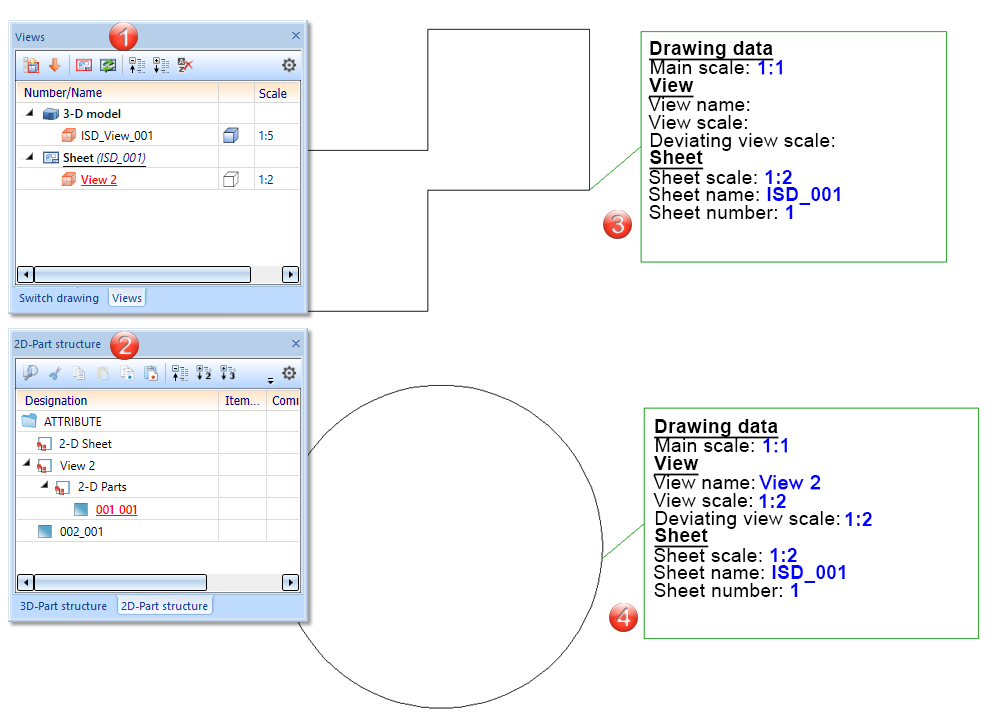
(1) Sheet view active
(2) 2D part structure in ICN
(3) Part 002_001 is on the same plane as "View 2", therefore no information about the View is displayed
(4) Part 001_001 is below "View 2", therefore Sheet and View information is displayed
3. Representation of the font
The following properties can be assigned to each text block of an annotation:
- Layer
- Character set (for different regions)
- Font,
- Font size,
- Text width coefficient
- Line spacing,
- Font colour and
- Aspect ratio and inclination of text.
HiCAD makes all installed Windows font types as well as special HiCAD fonts available for selection. There are proportional and non-proportional HiCAD fonts. The non-proportional HiCAD fonts are particularly suitable for tabular texts. The representation of the characters in the specified text size is independent of the scale of the drawing. The font size in the default text font refers to upper-case letters. HiCAD offers the nominal font sizes according to DIN EN ISO 3098-0.
The character set determines which fonts will be offered for selection, e.g. if you choose "Chinese", only fonts that support Chinese characters can be selected from the list box.
Text width coefficients and inclinations can only be specified for HiCAD fonts. The default value for the text width coefficient is 1.0. If the value is smaller than 1, the text will be horizontally compressed. if the value is greater than 1, the text will be horizontally stretched.
The values of the drop-down lists for font size, text width coefficient and line spacing can be arbitrarily expanded in the Configuration Editor at System settings > Annotations > Text > Preferred text sizes. After restarting HiCAD the new default settings will be used.
Each text can be placed in one of 1,000 layers. Layer 0 contains texts that are not displayed on the drawing. These are special texts that are only used to specify non-graphic attributes for parts, e.g. article data. The text layers are identical to the layers of the other elements and are not managed separately. The layer number is taken into account as an attribute during selection of active attributes.
The Aspect ratio and inclination of text field determines the style and the inclination angle of a text if HiCAD fonts are used. If the aspect ratio is smaller than 1 the text will be compressed. If it is greater than 1, the text will be stretched. If the inclination is 0.00 degrees the text will be shown in "Regular" style. If the inclination is 15.00 degrees the text will be shown in "Italic" style.
4. Insert, delete, move and display text blocks
A text block or an annotation may, in turn, consist of several text blocks, which can be differently formatted.
You use these functions to process the active text block.
| Functions for text blocks | |||
|---|---|---|---|
|
|
inserts a new text block (behind the active one) |
|
inserts a new text block in a new line |
|
|
deletes the active text block |
|
moves the active text block to the left |
|
|
moves the active text block to the right |
|
moves the active text block up one line |
|
|
moves the active text block down one line |
||


5. Representation of outer frame and leader line
In the Entire window pane, you define the display of the entire annotation. This includes:
- Frame for annotation

You can create the complete annotation with or without a frame, as well as underlined, i.e. with an extended tag.
- Dividing lines

The text lines can be separated by dividing lines.
- Annotation angle
If you want the part annotation (including the extended tag) to be created at a certain angle, then enter the angle you require.
- Leader line
If this checkbox is active, the annotation is created with a leader line. In this case you can define, beneath Lines, the display of the leader line, i.e. the Line colour, Line type, and the Base point, i.e. the symbol of the leader line.
- Reference/Insertion point
Enables you to specify the alignment of the leader line, which depends on the type of the selected total frame.
-
 If you choose a rectangular or circular frame, the leader line is automatically aligned to this frame.
 -
 If the annotation is underlined (by the leader line), the leader line can be aligned to the frame or - in the case of multi-line annotations - to a particular line. You can switch between the lines with the arrow keys
  .
. -
 For annotations without a total frame you can, in addition to the alignment to the frame or to a text line, also align the leader line to a specific text element of the annotation. You can switch between the text elements with the arrow keys.
For annotations without leader line, the alignment of the annotation is specified via the insertion point, which you select by activating the appropriate radio button.
 Please note:
Use the option at the bottom right of the dialogue to specify the number of decimal places for each numerical text block.
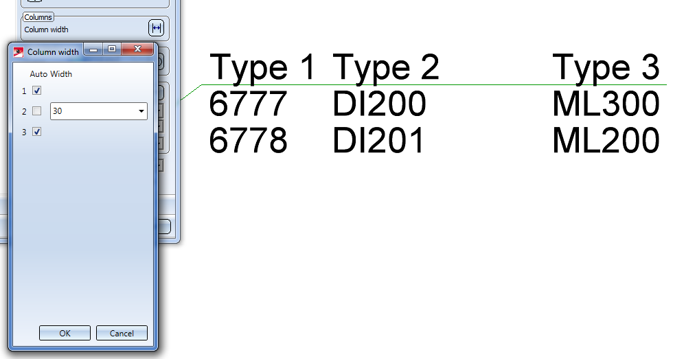
6. Columns
Click the  icon for Column width if you wish to change the column widths of tables. In the dialogue, deactivate the checkbox of the column the width of with you want to change and enter the desired width.
7. Representation of frame around text block
In the Text block area you can define the frames for the active rows forming the text block.The following options are available:

|
Active text block without frame |

|
Inserts a frame around text block |

|
Inserts a double frame around the active text block. |

|
Inserts a round frame around the active text block. |

|
Inserts a frame with rounded edges around the active text block. |
8. Properties of leader line
In the window area Lines you set the Line colour and the Line type for the leader line. Select colour and line from the list box. If you want to draw the leader line with a symbol (e.g. an arrow), select the required symbol from the Base point listbox.
You can freely select the size of leader line symbols, e.g. the arrow. The arrow size will be saved together with the drawing, thus retaining the symbol geometry, irrespective of the workstation. Furthermore, you can preset in the file POS3DPARNEU.DAT the angle and width of symbols (in addition to their length) as defaults.
Settings specified in the file POS3DPARNEU.DAT are default dimensions for the creation of new leader lines, and the changing of older leader lines for which no arrow dimensions have been saved yet.
9. Decimal places
For attribute values with decimal places you have the option to determine the number of decimal places at the bottom right of the dialogue. You can specify whether non-relevant decimal places (e.g. final zeroes) are also to be displayed by activating or deactivating the checkbox.
10. Background, Zoom and End Editor
|
OK |
The current settings are used as default settings for subsequently created annotation texts. |
|
Cancel |
Ends the function without applying the made settings. |
|
Background |
The background of the text input area is switched temporarily. This can be useful, for example, if it is difficult to see the selected font colour on the background. |
|
Zoom |
The zoom functions enable you to enlarge or downsize the text in the input window, or fit it to the entire width of the window. |
