> Dimensioning Settings
Steel Engineering > Further functions > Settings > Dimensioning Settings
For drawing derivations, the dimensioning of parts and assemblies normally takes place according to the dimensioning rules specified in the Configuration Editor (isdconfigeditor.exe) for the different usages. These settings apply even if the Drawing parameters: Set in dialogue option has been activated in the dialogue window for drawing derivations.
If you do not want to use any dimensioning rules you need to change the Usage configurations accordingly.
In the Configuration Editor, select ..> Automatic drawing derivation > Production drawing > Usage-dependent > NAME > Views, with NAME being the name of the corresponding usage, i.e. for example ASSEMBLY_BEAM, and set the Create dimensioning parameter to Conventional.
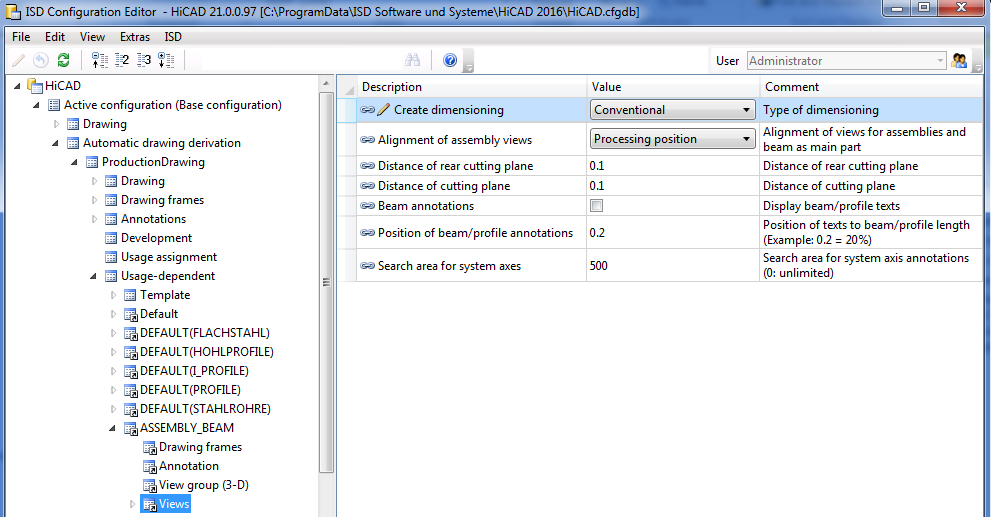
If the parameter is set to Conventional, not the settings in the Configuration Editor, but the conventional dimensioning settings from the STW_DimSettings.xml file in the HiCAD sys directory will be used.
This concerns:
When you call the function the Dimensioning Settings window is displayed. Select which settings window you want to activate by clicking the appropriate button.
The settings specified in this file can be changed via this dialogue window. After changing the settings, the parameters will immediately take effect. For a permanent saving, select File > Save as.
![]()
![]()
The Chains of dimensions window enables you to individually specify for:
to which views you want to apply the dimensionings. Click the Views... button to the right of the appropriate entry and select the desired views by activating or deactivating the corresponding checkboxes.
When you exit the window with OK, the Settings for dimensioning window is displayed again.
![]()
![]()
In this dialogue window you specify which bore and bolting diameters you want to dimension, and the way in which you want to dimension slots: Do not dimension, Length/Width or Centre/Diameter.
In addition, you can influence the position of dimensionings for bores/boltings. You can, for instance, specify whether you want to separate chains of dimensions for main parts and sub-parts, etc.
When you exit the window with OK, the Settings for dimensioning window is displayed again.
![]()
![]()
This function enables you to define various settings for the designation tags in a workshop drawing.
For example, you can select for bore designation tags whether you want to use the designation for the bore or for the appropriate bolt. Furthermore, you can add an auxiliary text consisting of up to 20 characters and you can determine whether the number of bores is specified or not.
In the lower part of the dialogue window you can select a different line type for the designation tag for sub-parts, bores or boltings on the back of a part.
When you exit the window with OK, the Settings for dimensioning window is displayed again.
![]()
![]()
Use this function to specify the type of dimensioning in the workshop drawing. Possible are:
The selection can be separately applied to
When you exit the window with OK, the Settings for dimensioning window is displayed again.
![]()
![]()
Use this function to define general settings.
Examples are:
When you exit the window with OK, the Dimensioning Settings window is displayed again.
![]()
Related Topics
Settings/Management (3-D SE) • Steel Engineering Functions
|
Version 2102 - HiCAD Steel Engineering | Date: 15/11/2016 | © Copyright 1994-2016, ISD Software und Systeme GmbH |