"Civil Engineering functions" docking window > Steel Engineering > Connections > Front side to web/flange side > Front plate > Column connection, Frame corner (203)
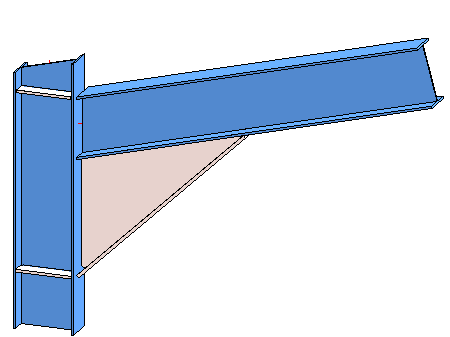
Use this function to connect two beams with a bolted or welded beam frame corner. You can create the frame corner with or without stiffeners, haunched plates or other components.
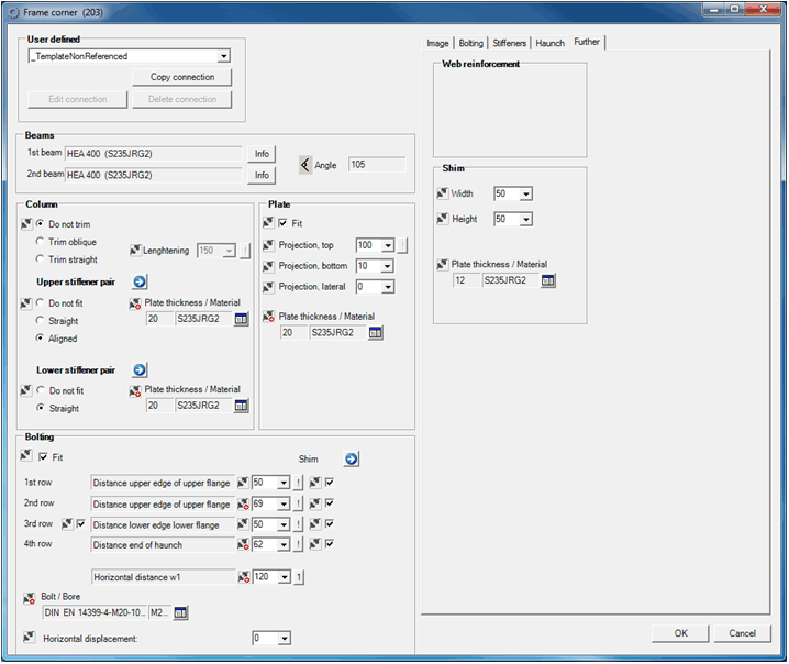
Requirements for the creation of frame corners are as follows:
|
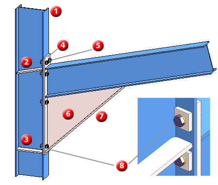
(1) Column (untrimmed) |
(5) Bolting |
|
(2) Upper stiffeners, aligned |
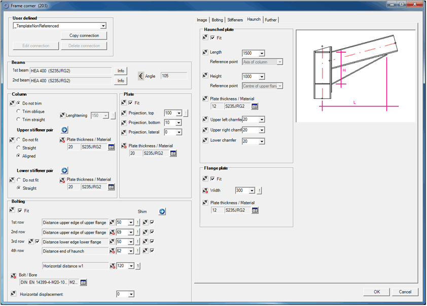
(6) Haunched plate |
|
(3) Lower stiffeners, straight |
(7) Flange plate |
|
(4) Plate |
(8) Shim |
Proceed as follows :
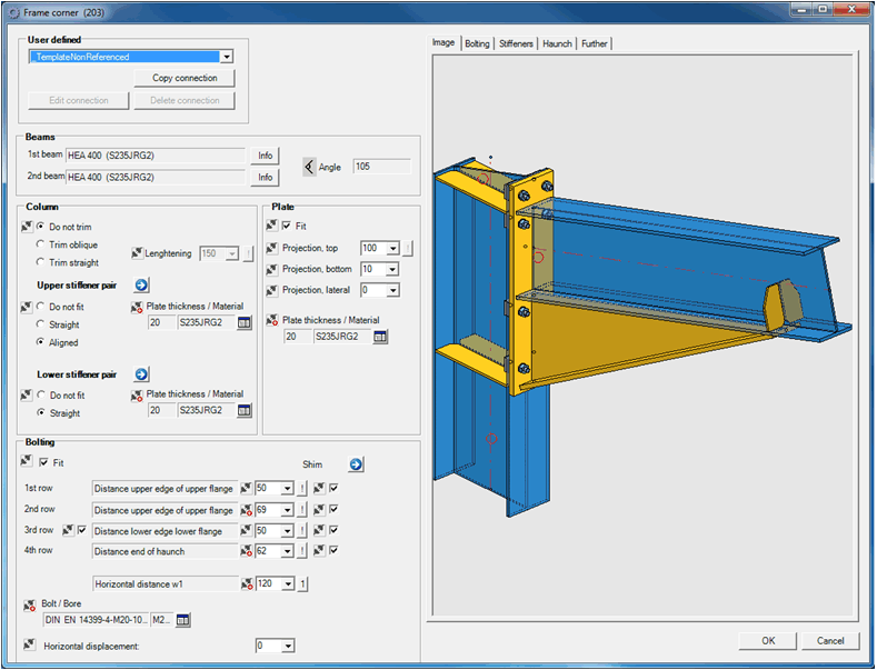
Select the desired configuration. The input fields contain pre-set values depending on the selected configuration. You can modify these values if required. Please note however that the editing of the fields depends on the respective type indicator!
When trimming the column, the lengthening determines the projection of the column relative to the connected beam.
If you want the column to be flush with the plate of the frame corner, click the  symbol.
The upper stiffeners can be fitted straight or aligned relative to the connected beam. The lower stiffeners can only be fitted straight.
Click the  symbol to activate the Stiffeners dialogue window and set further parameters for stiffeners. If you do not want any stiffeners, select the Do not fit option.
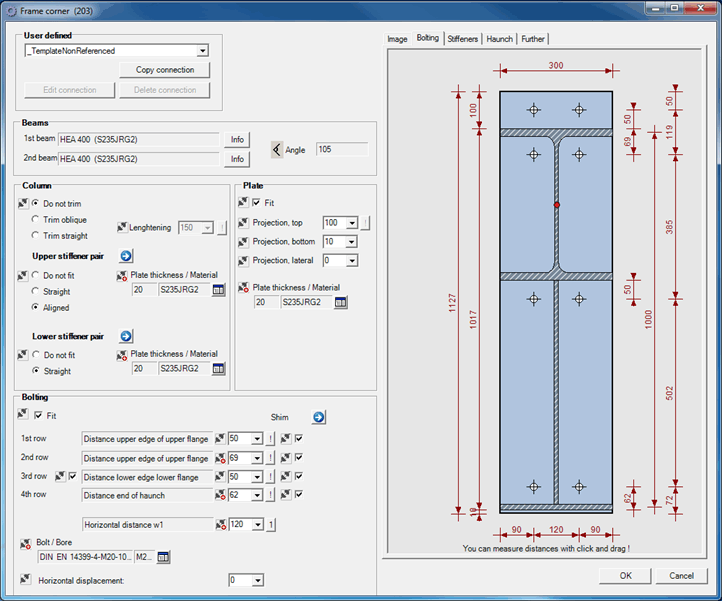
For bolted frame corners you need to specify the Bolting parameters. These are the Bolting/Bore type (can also be accessed by clicking  and selecting from the Bolting menu) and the distances of the bolting rows. Use the symbol to align the rows symmetrically relative to the flange or haunched plate. The preview image on the Bolting tab is automatically adjusted to the current settings.
If you want to displace the bolting horizontally, enter the value for the horizontal direction. .If the value is 0, the bolting is aligned centred.
If you want to additionally reinforce the bolting with a shim, click the symbol to activate the Further tab. Here you can specify the required settings.
 Please note:
![]()
Related Topics
Connections + Variants (3-D SE) • Dialogue Window for Connections -Type II (3-D SE) • The Catalogue System for Connections + Variants (3-D SE)
|
Version 2102 - HiCAD Steel Engineering | Date: 15/11/2016 | © Copyright 1994-2016, ISD Software und Systeme GmbH |