'Civil Engineering functions' docking window > Steel Engineering >Stairs + Railings > Railing> Railing Configurator (Railings along beams)
Please note the following when using the Railing Configurator, especially when creating workshop drawings for railings:
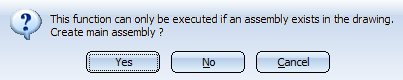
Select Yes if you want to create a new main assembly. In this way, railings along beams can be directly inserted. Please note that parts which already exist in the drawing will not automatically be moved below the created main assembly. Therefore, the following message will appear if you select already existing beams:
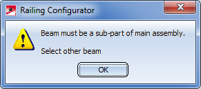
Click OK. After the manual moving of the beam below the main assembly, select the railing function again.
 before calling the Railing Configurator.
DEpending on the selected railing function, a feature log item called
Railing along beams or
Railing along edges, respectively,
will be entered into the feature log.
To process an already existing railing, identify one of the railing elements and double-click Geländer entlang Kanten or Geländer entlang Profilenin the feature log. The Railing Configurator will then be started.
An assembly called Railing will be created for the railing. This assembly is made up of sub-assemblies called Segment, which in turn contain the railing elements of the individual beams. The Segment sub-assembly is subdivided into the following sub-assemblies:
 Important:
If there are several beams in succession that are aligned in the same direction, the railing elements of these beams will be combined into one segment assembly. As a result, continuous hand rails and knee rails will be formed on these beams. The updating and modification of existing railings (before Version 2016 SP2) will still be performed with separate segment assemblies and non-continuous hand rails and knee rails.
Example:
Let us assume that you want to place a railing on beams (1) - (6). The beams (3) and (4) are aligned in the same direction. In this case, the assembly "Railing" will consist of 5 "Segment" sub-assemblies. As a result, the railing elements of beams (3) and (4) have been combined into one railing segment, with continuous hand rails and knee rails.
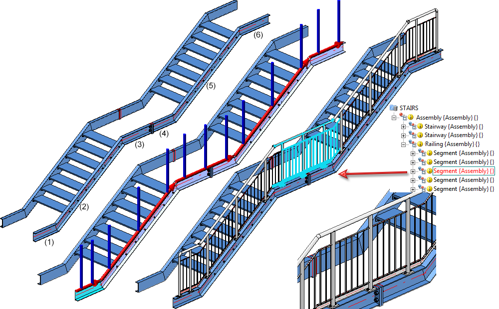
Versions before HiCAD 2016 SP2 would have created 6 "Segment" assemblies, with two separate railing segments for the beams (3) and (4), i.e. one for beam (3) and one for beam (4).
The BOM-relevance of the assemblies to be created by the Railing Configurator can be set in the Configuration Editor (isdconfigeditor.exe), at Steel Engineering > Products > Railing, separately for
The default setting is as follows:
If you deactivate the BOM-relevance for the component assemblies, no assembly main parts will be defined by the Railing Configurator.
|
Assembly |
Usage |
BOM-relevant? |
Utilized configuration |
Consider for drawing derivation? |
|---|---|---|---|---|
|
Railing |
Railing |
Yes |
RAILING |
No |
|
Segment |
Railing segment |
Yes | RAILING_SEGMENT | Yes |
|
Post |
Post |
Yes | POST | No |
|
Handrail |
Handrail |
Yes | STRINGER | No |
|
Infill |
Infill |
Yes |
FILLING |
No |
| Boom |
Boom |
Yes | STRINGER | No |
|
Kneerail |
Kneerail |
Yes | STRINGER | No |
|
Vertical rod |
Vertical rod |
Yes | STRINGER | No |
|
Skirting board |
Skirting board |
Yes |
DEFAULT |
Yes |
The configurations for railings created via drawing derivation are stored in the Configuration Editor (isdconfigeditor.exe) at Automatic drawing derivation > Production drawing > Usage-dependent. The dimensioning rules for the railing segments can be found at the respective Set of dimensioning rules entry, e.g. Automatic drawing derivation > Production drawing > Usage-dependent > RAILING > Set of dimensioning rules.
The assemblies Railing, Railing segment, Handrail, Post and Filling possess reliable coordinate systems which can be used for the determination of the views and the dimensioning of derived drawings.
At the time of assembly creation, the origin of the assembly coordinate systems is located in the origin of the world coordinate system.
Railing segments can be displayed in fitting position or in processing position in workshop drawings. The fitting position makes sense for inclined railings, the processing position should be used for railings in X-direction, i.e. with horizontal handrail.
When assigning designations to the vertical rods in the Segment views, only one designation (Item number) will be generated for several identical parts, i.e. identical rods in one view will obtain one designation (item number), while the other parts of the railing will be designated individually.
The main annotation tags of the Railing assembly are defined by the template file WSD_RailingAssembly.FTD. The file contains the Usage and Item number attributes. Sub-part tags are defined by the template PosNummerSTB_Nebenteile.FTD.
 Please note that the German or English names (not the key names) of the tree structure are used for references to the Configuration Management!
![]()
Related Topics
|
Version 2102 - HiCAD Steel Engineering | Date: 15/11/2016 | © Copyright 1994-2016, ISD Software und Systeme GmbH |