![]()
Steel Engineering > Plate, new > Glass 
You use this function to fit glass panes into frameworks. Fitting can be one-sided or two-sided. The prerequisite is for you to set glass points which define the glass thickness. Series beams are used to create the frame.
![]() Glass panes for non-closed beam frames can also be generated
automatically. Select Further functions > Settings
Glass panes for non-closed beam frames can also be generated
automatically. Select Further functions > Settings  > Glass insertion> End points to define how you
want the open ends to be closed:
 For glass insertion the default settings of the Default glass function are used. If it is not possible to use these settings, e.g. because the glass thickness determined by the glass points is too great or too low, the dialogue window Glass structure is displayed. Here you can either modify the values accordingly or define new glass panes.
Create series beams for frame
For the glass fitting to be carried out automatically, the cross-section of the series beam used must exist as a 2-D part (figure) or as a 2-D DXF file and fulfil certain prerequisites.
For automatic glass fitting, a sub-part GLASS which consists only of isolated points, i.e. the glass points, also needs to be created. These points define the glass thickness and the distance from the axis. Furthermore, you also specify the direction of the geometry shift for variable glass thickness
Unique point numbers need to be assigned to the isolated points for glass fitting. For one-sided glass fitting, glass points 10,11,12 need to be defined; for two-sided fitting, glass points 20,21,22 need to be defined in addition. Please make sure that you keep to this designation, as HiCAD cannot determine the glass points otherwise.
Procedure
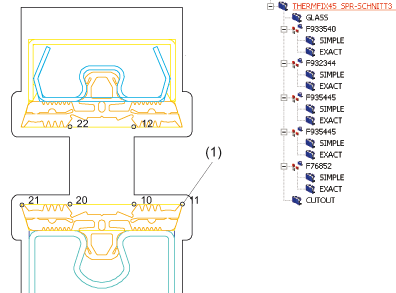
2-D figure with glass points (1) for a Forster series beam (extract)
Fit glass to frame
If a closed frame of series beams with glass points exists, you can use the Glass insertion function to start the glass fitting automatically.
The glass is inserted into the part structure as a main part with the article number (designation) GLASS nn, where nn is the glass thickness which is defined by the glass points assigned in the 2-D figure.
The figure shows a frame of Forster series beams, to which the glass
has been automatically fitted.
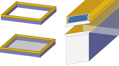
Left: Frame with automatically fitted glass, Right: Extract of glass in the frame (Forster beam)
![]()
Steel Engineering > Plate, new > Glass  > Glass, from sketch
Use this function to derive single or multiple glazings from sketches in the drawing. You can also select a side for coating.
When you call the Glass from sketch function, the Glass structure dialogue window will be displayed.
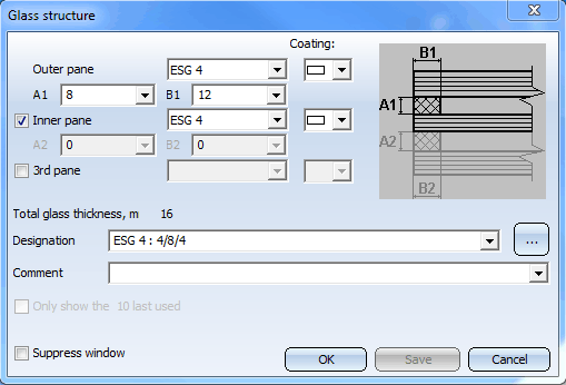
Here you can define your own configurations for glass panes, or use the configurations supplied with HiCAD. The configurations are managed in the GLASS PANES ISD table of the FACTORY STANDARDS > GLASS PANES catalogue.
Using the ISD default configurations
To use one of the default configurations supplied with HiCAD, click the  icon and select the desired configuration. The pre-defined settings will then be displayed in a dialogue window.
Defining your own configurations
You can also define your own configurations if desired.
First specify, via activation or deactivation of the corresponding checkboxes, whether the glazing should consist of one or several panes. For each pane you can choose the desired glass type from a list box. The available glass types are defined in the catalogue MATERIALS > GLASS. In the Coating field, the coating type defined in the catalogue for this glass type is displayed. If the type One-sided has been assigned to this glass type, you can choose whether the coating is to be apply at the bottom or at the top.

If a  symbol is displayed in the Coating field, this means that no coating type has been assigned to this glass type.
For multiple glazings you specify, via the fields A1/B1, and A2/B2, the distance between the panes:
|
A1 |
Spacing between 1st and 2nd pane |
|
B1 |
Width of 1st intermediate frame |
|
A2 |
Spacing between 2nd and 3rd pane |
|
B2 |
Width of 2nd intermediate frame |
The total glass thickness will be automatically determined by HiCAD and displayed in the dialogue window.
To save your configuration, enter the name of the configuration in the Designation field and click Save.
To insert the glass with the current settings, close the dialogue window with OK.
HiCAD prompts you to select the sketch for the glass. If you want the sketch to be deleted immediately after glass insertion, confirm the prompt with Yes. If you want the sketch to be retained, select No.
HiCAD then shows you a preview of the glass and prompts you to specify a fitting point on the glass. Besides the glass ID, a cross-shaped figure will be displayed on the glass. Now select a point on the glass and specify the position of this point in your drawing.
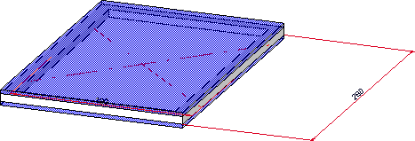
Glass with Glass ID
You can then insert more glasses, or end the function by pressing the MMB.
Glass objects created with this function obtain the name of the configuration used as "Article number", and the part type Glass panes.

 Important:
The assigning of the coating types to the glass types takes place in the GLASS TYPES table of the catalogue MATERIALS > GLASS. There you will find the column COATING. To assign a coating to a glass type, double-click the corresponding field and select the desired coating type from the list box.
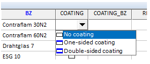
Please do not forget to save the table. Extensive information on the editing and processing of catalogues and tables can be found Online Help for the Catalogue Editor.
 Please note:
 > Glass insertion > Default glass.
 Related Topics
Plates (3-D SE) • Steel Engineering Functions
|
Version 2102 - HiCAD Steel Engineering | Date: 15/11/2016 | © Copyright 1994-2016, ISD Software und Systeme GmbH |