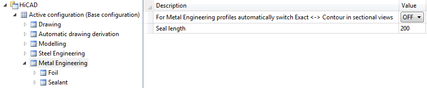
Beams can be represented both in simplified form and exactly. The simplified representation does not, for example, display the radii of beams. Furthermore, you can also define whether you want beam annotations, axes and their end points as well as tracing lines of beams to be represented. This allows you, for example, to show and hide beam annotations separately in the workshop drawing and in the 3-D model.
Representation options (from left to right):
exact - simplified - only axes - beam with axes (1) and tracing lines
There are various options for defining the representation type of beams:
 . In the Representation tab of the dialogue window, define the desired settings, which
will apply to all subsequently created beams.
. In the Representation tab of the dialogue window, define the desired settings, which
will apply to all subsequently created beams.  > Exact <-> Simplified or Auxiliary lines. > Beam/profile axes > Show/Hide, and choose the desired function.
Changing the representation type via feature log
You can also use the feature log to change the representation type – by double-clicking Representation. In the window that is displayed, activate the desired option field and choose OK to exit the window.
Also available here is the Enter formula option, which you can use to assign a variable to the representation type. An example of a typical use case would be, for example, a beam with bores which you do not want to be visible in the simplified representation. Proceed as follows:
The bores are then immediately hidden. If you then choose the Variables of the feature function and assign 1 to the variable EXA, the exact representation is activated – with the bores.
 Please note:

Related Topics
Steel Engineering Settings (3-D SE) • General Information (3-D SE)
|
Version 2102 - HiCAD Steel Engineering | Date: 15/11/2016 | © Copyright 1994-2016, ISD Software und Systeme GmbH |