Civil Engineering functions docking window > Steel Engineering >Stairs + Railings > Railing > Railing Configurator (Railings along beams)
The Railing Configurator of the HiCAD Steel Engineering module enables you to configure and insert individual railings along beams, e.g. for staircases created with the Staircase Configurator, or various platforms.
Before using the Railing Configurator, please read the information given in the Railing Configurator - Important Notes topic.
As this function is rather complex, the settings will initially be explained by means of a simple staircase example. How to proceed for multi-storey stairs and railings with equidistant railing posts is explained in a separate example.
First, a railing is to be added to the staircase that has been generated with the Railing Configurator (Stringers: U280 beams). Please note that in this example, the ISD default settings are used.
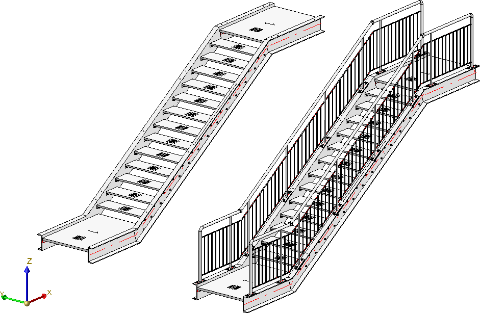
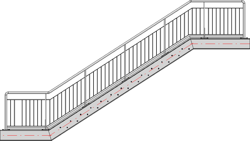
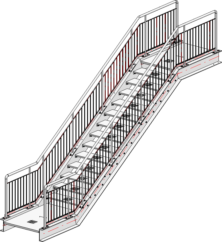
Simple staircase with railing
Before starting the Railing Configurator, please make sure that the coordinate system is aligned correctly. The Railing Configurator aligns the railings to the Z-axis. If you are not sure, select Drawing > Others > World CS  to activate the 3-D World Coordinate system (=default CS).
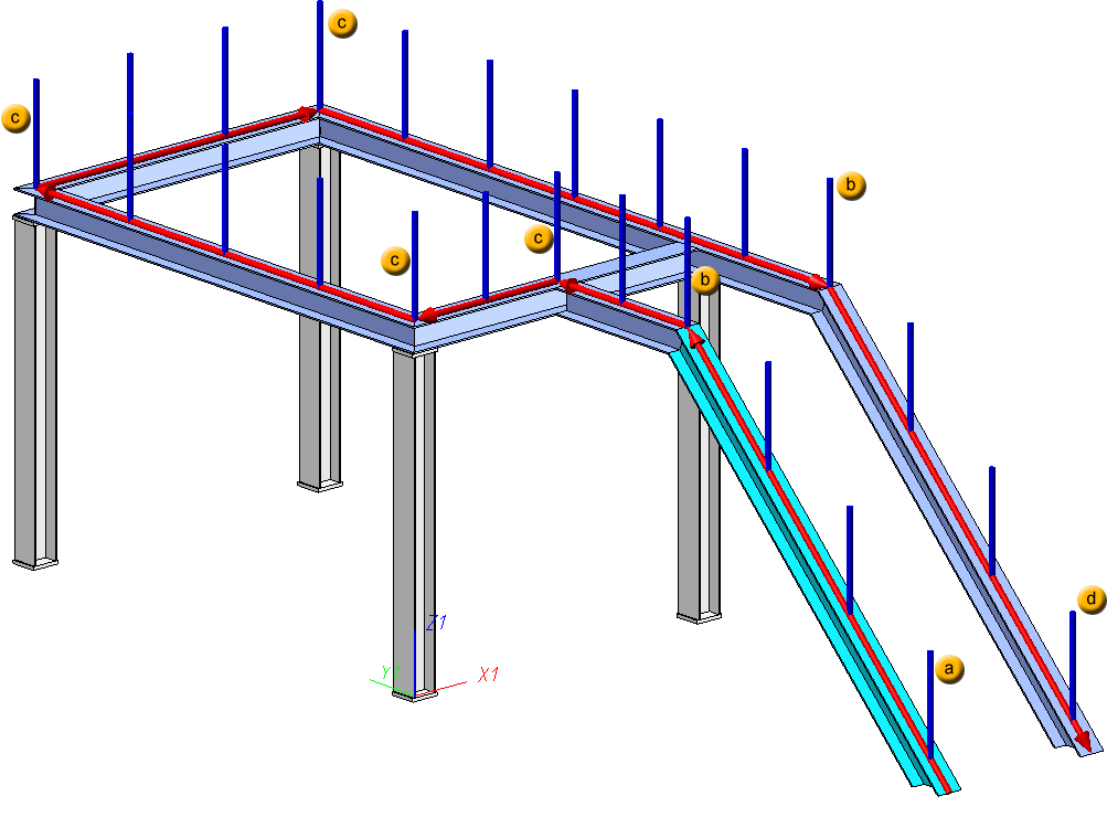
After calling the Railing Configurator you will be prompted to identify, one by one, the Steel Engineering beams onto which the railing is to be placed. The "path" that is formed by the beams will define a virtual composite edge that will serve as a guideline for the route of the railing. Posts, handrail, infill and knee rails will then be located on a composite edge running parallel to this guideline.
When selecting the beams, please note that HiCAD interprets the first selected beam as the start, which the later partitioning of the railing will be based on (fixed distance with rest at start or end). In practice, engineers mostly use an upstairs walking direction as an orientation.
During selection of the beams, the walking line and walking direction will be visualized by means of a red arrow. This walking line determines the height and the fixing position of the railing. The distribution of posts, too, will be visualized according to the last selected settings. As soon as you change the settings in the dialogue window, the preview will be updated.
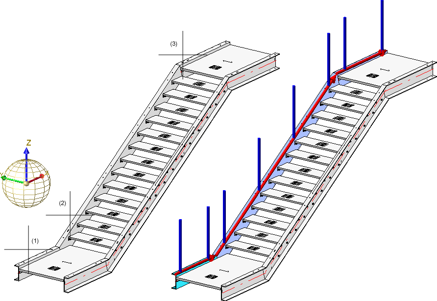
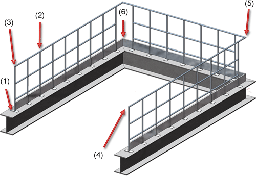
 Example, Step 1 - Selection of beams (1), (2) and (3) -> Walking line and direction will be visualized
You end the selection of beams by clicking the middle mouse button. This automatically opens the Railing Configurator dialogue window.
This dialogue window consists of the following tabs:
General parameters and component selection:
Parameters for the definition of the railing components:
The settings can be saved as Favourites and reused at any time. At the bottom left of the dialogue window, click the  symbol to activate a menu with Favourites functions. More information about Favourites can be found in the Manage Favourites topic of the HiCAD Basics Help.
While the window is open, you can display a Preview of the railing generated with the current settings by clicking the same-named button. You can use the zoom functions to enlarge or downsize the object on the screen.
Click OK to start the generation of the railing. The progress of the generation will be indicated in a progress bar.
 Please note:
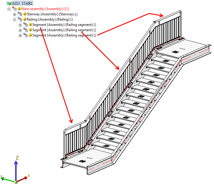
If there are several beams in succession that are aligned in the same direction, the railing elements of these beams will be combined into one segment assembly. As a result, continuous hand rails and knee rails will be formed on these beams. The updating and modification of existing railings (before Version 2016 SP2) will still be performed with separate segment assemblies and non-continuous hand rails and knee rails.
 icon to directly choose the component from the HiCAD catalogue and specify all required settings.
  and
and  symbols to open and close input areas.
![]()
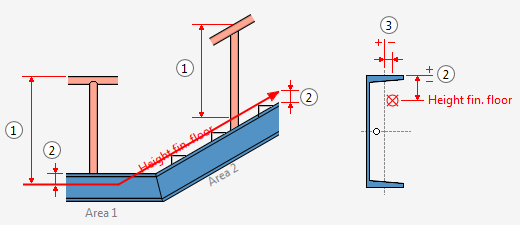
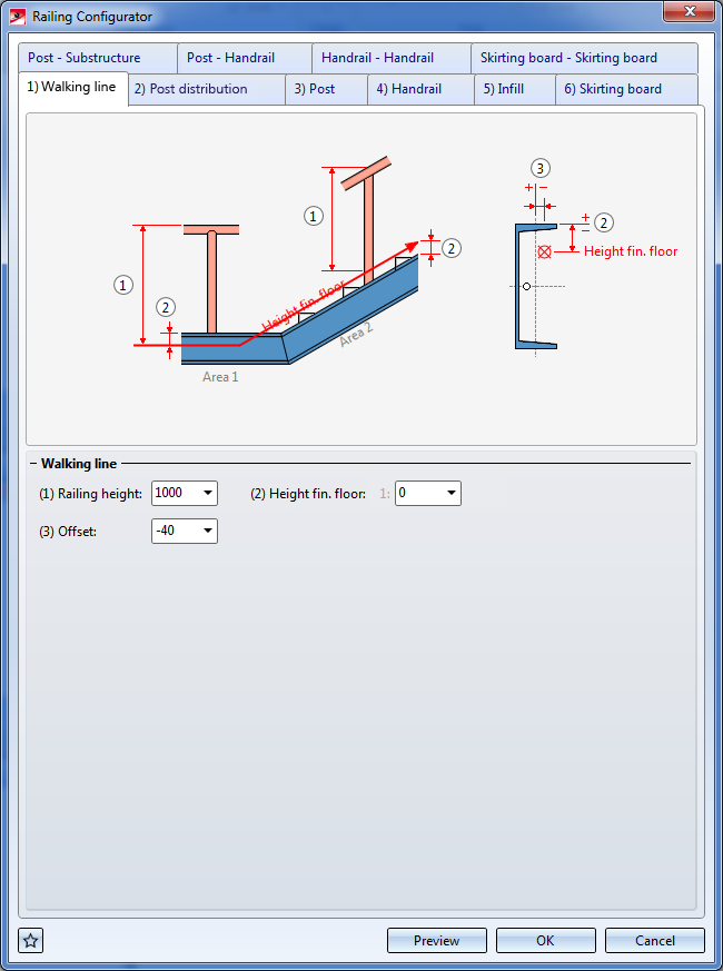
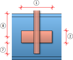
Railing height (1)
This value determines the railing height from the finished floor. This height always refers to the top step corner.
Height fin. floor (2)
This value determines the distance between the upper beam side and the finished floor. If you enter a value greater than 0 or less that 0, the entire walking line will be moved upwards or downwards. Depending on the type of the selected beams you can also specify different heights for the finished floor. For this purpose, the selected beams are subdivided into areas. The first beam belongs to area 1. HiCAD will then check whether the next beam is located in the same plane. If this is the case, it also belongs to area 1. If not, area 2 starts with this beam etc. For each of these areas the value Height fin. floor can be specified separately.
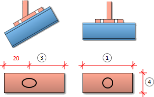
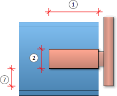
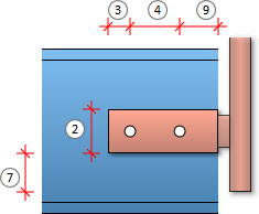
Offset (3)
Here you specify the lateral distance to the beam axes - seen in positive direction to the left / negative direction to the right in walking direction (3)
Please note that you can also take the values directly from the drawing by right-clicking the input field and selecting Pick distance.
![]()
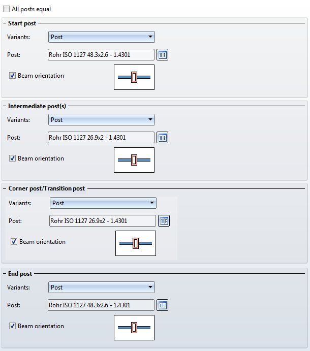
On this tab you specify which posts are to be created, and how the posts are to be distributed along the walking line.
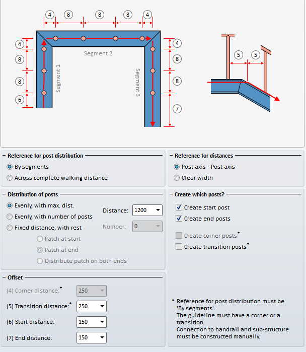
One distinguishes between start post, end post and transition post.
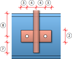
Reference for post distribution
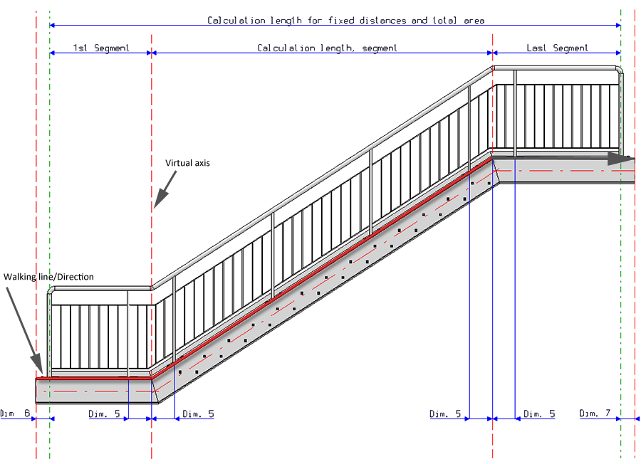
The distribution of the posts can take place by segments or across the complete walking distance. A segment is the length between the virtual axes, i.e. the perpendiculars in the corner points or inflexion points of the red walking line.
The By segments setting makes sense for the creation of balcony railings. Here, the posts will be evenly distributed to the corners, and the corner fields are also filled evenly .
On the other hand, the Across complete walking distance setting can be useful for the creation on railings on staircases, e.g. for multi-storey staircases and railings with equal post distances.
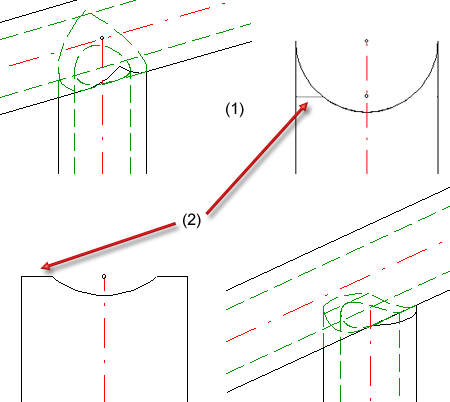
A segment is the length between the virtual axes (i.e. the perpendiculars in the inflexion points of the red line, pls. see image below), e.g.:
Distribution of posts
If you select this option, the Start distance (Dimension 6) and the End distance (Dimension 7) will be subtracted from the total length of the walking line. The rest will be distributed in such a way that the distances between the posts will be equal and will not exceed the specified maximum distance. The Transition distance (Dimension 5) will not be considered.
Here, the calculation length will be divided by the number of posts, with regard to the axis length. The value in the Distance field as well as the Transition distance (Dimension 5) will not be considered.
If you select this option, you need to check whether the remaining rests (patches) are to be located at the start, at the end or on both sides. It is therefore recommended to use "virtual" vertical auxiliary lines during the construction process. For if the railing posts are to be located below one another after completion of the construction, this can be achieved easiest with this option. This means that the specified dimensions will only be used for the active flight of stairs (walking line). In the sketch you can see that the flight of stairs 1 places Dimension 6 at the bottom right (at the start), and Dimension 7 at the left. When you activate the flight of stairs 2, Dimension 6 will be located on the left, and Dimension 7 on the right. This should be taken into account to ensure that the correct distances will be entered. Dimension 5 will not be considered.
When selecting the beams, please note that HiCAD interprets the first selected beam as the start, which the later partitioning of the railing will be based on (fixed distance with rest at the start or end). In practice, engineers mostly use an upstairs walking direction as an orientation.
For the distribution of posts in the image this means:
Example: Distribution of posts by segments
Example: Distribution of posts across complete walking distance (different at transitions)
Reference for distances
The distance can either be interpreted as
Offset
Create which posts ?
Here you specify by activating the corresponding checkboxes which posts are to be created. The creation of Die Erzeugung von Eck- und Übergangspfosten ist nur möglich, wenn unter Bezug für Pfostenaufteilung die Option Segmentweise aktiv ist und die Leitlinie eine Ecke bzw. einen Übergang hat.
Example, Step 2 - Specify parameters on Walking line (1) and Post distribution (2) tabs
In our example the ISD default settings (with max. post distances, distribution of posts by segments) will be used, with the exception of the Offset value on the Walking line tab. The railing is to be plced in a centred position on the upper beam side. Therefore, select Offset = 0 here.
![]()
One distinguishes between Start posts, Intermediate posts, Corner/Transition posts and End posts. You can use all beams and factory beams for the variant supplied by the ISD.
You can change the Beam orientation by activating or deactivating the same-named checkbox.
If you ant to use the same variant for all posts, activate the All posts equal checkbox.
Please note:
Even if you activate the All posts equal checkbox here, the settings on the tabs Post - Substructure and Post - Handrail will not be considered for corner posts and transition posts! The connections on corner posts and transition posts must therefore be reworked manually.
Pleas note:
Value inputs in the Corner post/Transition post area will only be possible if the By segments option has been selected beneath Reference for post distribution on the Post distribution tab, and if the guideline has corners or transitions.
![]()
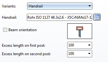
The variant supplied by the ISD allows an utilization of steel pipes as handrails. In addition, you can specify an excess length for the handrail at the start post and the end post. However, the excess length will only be evaluated if you have selected the variant <do not create>, Trim pipes or Connection with mandrel on the Post - Handrail tab.
If you want the beam height to be perpendicular the the railing plane, activate the Beam orientation checkbox.
![]()
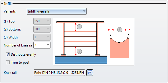
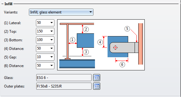
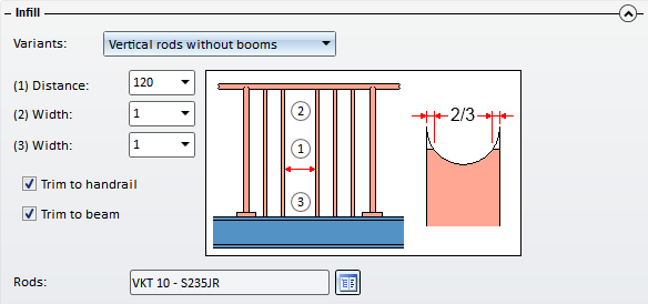
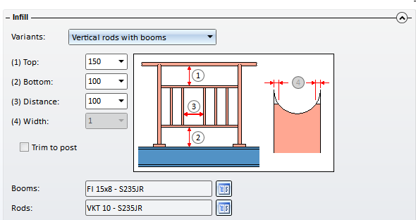
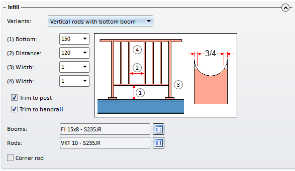
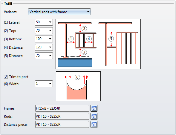
You can choose knee rails, glass elements, vertical rods with or without booms, vertical rods with bottom boom, or vertical rods with frame. The infill for corners and transitions (staircase/platform) can be defined separately. However, this is only possible if the guideline has corners and transitions and if the checkboxes for the creation of corner and transition posts have been deactivated on the Post distribution tab.
Kneerails
The kneerails can either be distributed evenly, or trimmed to the posts (activate same-named checkbox).
Glass elements
Allowed glass elements are the glass panes from the catalogue Factory standards > Glass panes, allowed external claddings are flat steels.
Vertical rods
Here you can define vertical rods, in addition to the knee rails.
For vertical rods with booms, bottom boom or frame, you select the booms, the bottom boom or frame, complete with rods and spacers from the catalogue.
For round to round connections you can also specify the parameter Width, referring to the width of the obtuse end.
![]()
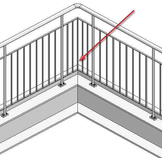
If you want to place rods in corners of beam frameworks, activate the Corner rod checkbox. A rod will then always be placed exactly in the corner as shown below:
Please note that rods can only placed in corners are only possible if there are no corner posts.
![]()
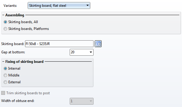
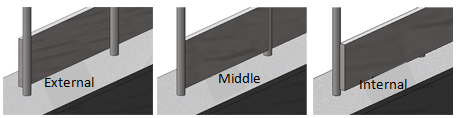
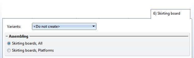
Available are skirting boards of flat steel.
Beneath Assembling you can specify by activating the corresponding option whether the skirting boards are to be used everywhere, or only on platforms, i.e. only in the horizontal area, with oblique trimmings (see image below).
Enter the distance between skirting board and upper beam side in the Gap at bottom input field, and specify the fixing of the skirting board.
Example - Step 3 - Component selection
In our example we will apply the ISD settings - with one exception - the railing is to be created without skirting boards.
![]()
Besides the components, you can create the following connections via the same-named tabs:
If you do not want to create a connection, select the <do not create> option in the corresponding selection box.
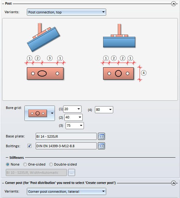
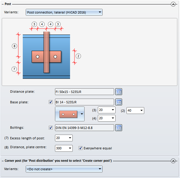
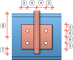
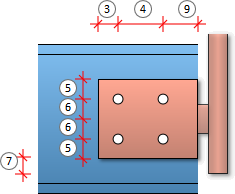
Here you specify the fixing of the posts to the beams The posts can either be mounted on top of the beam (top) or to the side of the beam (lateral) - with or without stiffeners. A bore grid can also be selected - possible options are:
Depending on the selected bore grid, the possible options are:
| Bore grid |
Input values |
|
|---|---|---|
| No bore |
|
|
| 2 bores |
|
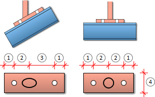
|
| 4 bores |
|
|
Depending on the selected bore grid, the possible options are:
| Bore grid |
Input values |
|
|---|---|---|
| No bore |
|
|
| 2 bores |
|
|
| 4 bores |
|
|
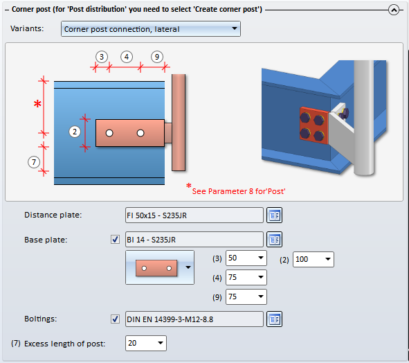
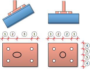
If you have activated the Create corner posts checkbox on the Post distribution tab, you can specify the corner post connections here. The following variants are possible:
Depending on the selected bore grid, the possible options are:
| Bore grid |
Input values |
|
|---|---|---|
| No bore |
|
|
| 2 bores |
|
|
| 4 bores |
|
|
Please note:
Even if you activate the All posts equal checkbox on the Post tab, the settings on the tabs Post - Substructure and Post - Handrail will not be considered for corner posts and transition posts! The connections on corner posts and transition posts must therefore be reworked manually.
![]()
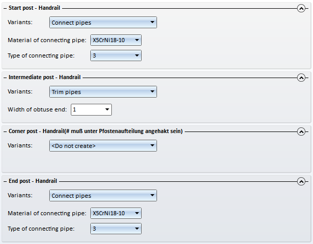
Here you specify the connection of post and handrail.
|
Allowed connections |
|||
|---|---|---|---|
|
Start post - Handrail (3) |
Intermediate post - Handrail (2) |
Corner post - Handrail (2) |
End post - Handrail (4) |
|
|
|
|
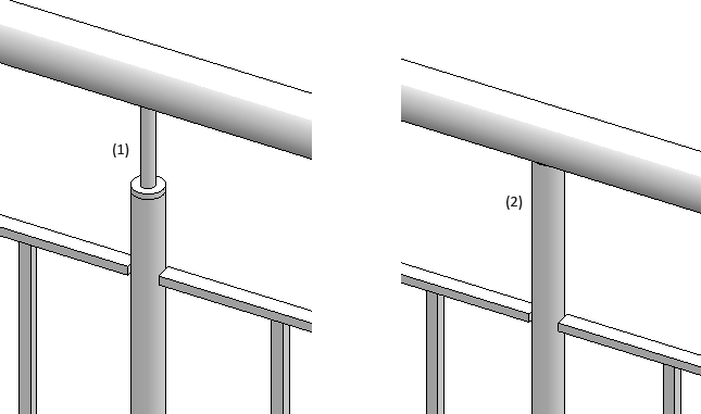
Example of a connection Intermediate post - Handrail: 1) Connection with mandrel, (2) Trim pipes
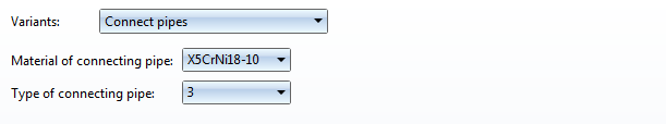
For the Connect pipes variant you need to choose the material for the connecting pipe and then its type. The latter determines the bend radius:
For round to round connections the parameter Width of obtuse end can be specified if the Trim pipes option has been selected. Normally, a pointed end (1) is created on the pipe after the trimming. Use the Width of obtuse end(2) parameter to specify how the pointed end on the post is to be cut off.
Please note that a connection of corner posts and handrails is only possible if the Create corner posts checkbox has been activated on the Post distribution tab.
![]()
Here you define the connection of the handrails. Allowed connections are:
Here you define the connection of the skirting boards. Here, mitre cuts are possible.
Example, Step 4 - Selection of connections
Use the ISD default settings and close the dialogue window with OK. The first railing will be inserted.
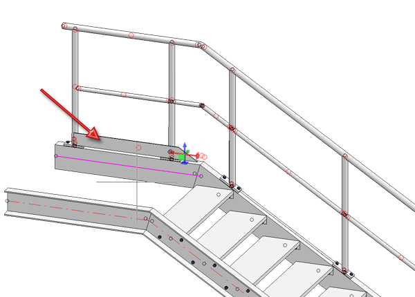
Example, Step 5 - Repeat Step 1 to Step 4 for the right stair stringer
Complete the example by repeating Steps 1 to 4 for the right stair stringer. Call the railing Configurator again and identify the right stringer beams (1) and (2).
The last chosen parameters will be shown in the Railing Configurator dialogue window. With the exception of the Offset, which needs to be entered in negative Y-direction here, apply all of those settings by clicking OK. The railing will then be generated.
Finished railing
An example and tips for the placing of railings with equal post distances on multi-storey staircases can be found here.
![]()
Related Topics
Railing Configurator - Railings Along Edges • Steel Engineering Functions
|
Version 2102 - HiCAD Steel Engineering | Date: 15/11/2016 | © Copyright 1994-2016, ISD Software und Systeme GmbH |