Value
Description
Designation / Rule Identifier
1
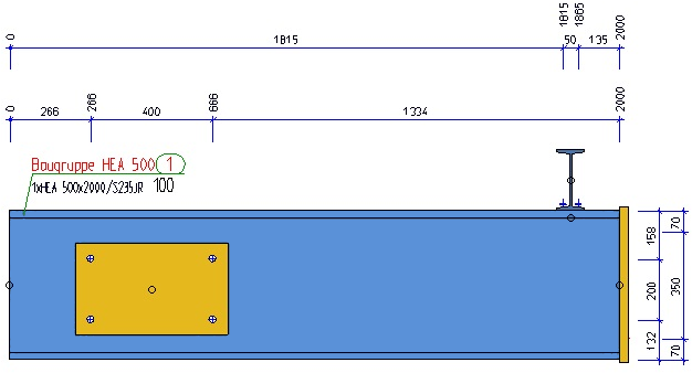
Length between system axes
SYSTEMLENGTH
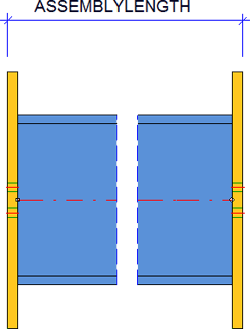
2
Assembly length
ASSEMBLYLENGTH
3
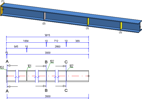
Axis length
LENGTH_OF_AXIS
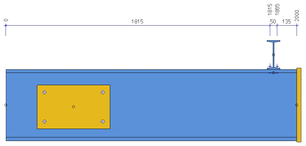
4
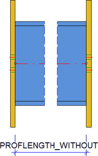
Beam length without front-mounted attached parts
PROFLENGTH_WITHOUT
5
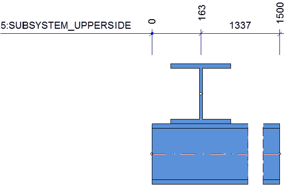
Sub-system, Upper beam side
PROFSYSTEM_UPPERSIDE
Only beams with cross-sections || to screen plane, || to beam axis
6
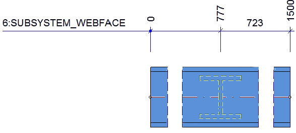
Sub-system, Web surface of beam
PROFSYSTEM_WEBFACE
7
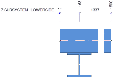
Sub-system, Lower beam side
PROFSYSTEM_LOWERSIDE
8*
Attached parts (via outer contour)
ATTACHING_PARTS
via outer contour, not via bores
9
Beam/profile length with front-mounted attached parts
PROFLENGTH_WITH
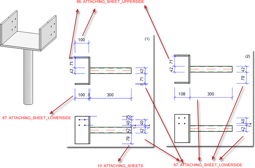
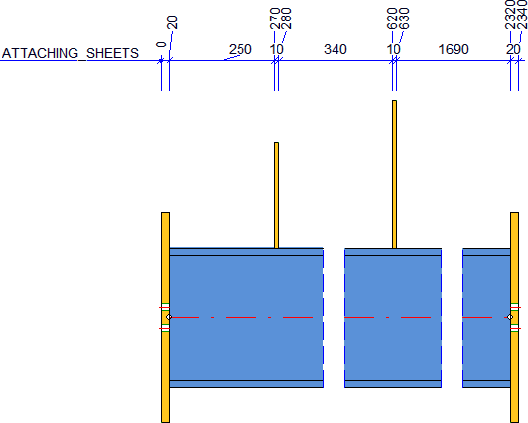
10*
Attached sheets/plates with bores
ATTACHING_SHEETS
Attached sheets/plates via bore or outer contour
11
Bores in sub-parts
SUBPARTBORES
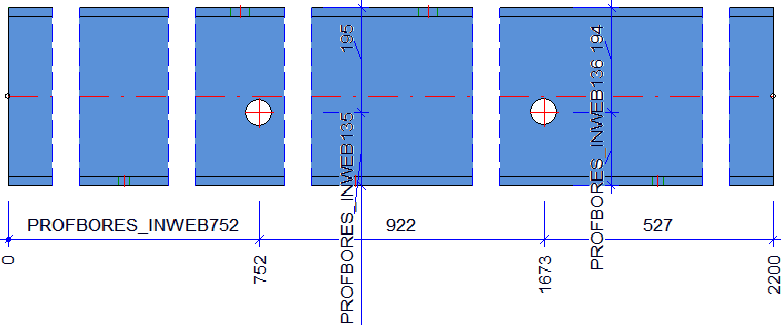
12
Bores in web of beam
PROFBORES_INWEB
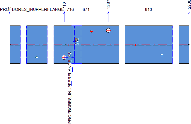
13
Bores in upper flange of beam
PROFBORES_INUPPERFLANGE
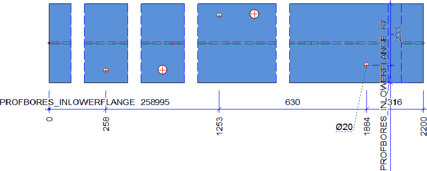
14
Bores in lower flange of beam
PROFBORES_INLOWERFLANGE
15
Bores in upper and lower flange of beam
PROFBORES_INFLANGES
16
16: Bores in beams - Offset parallel to beam axis
PROFBORES_SYSTEMOFFSET_PARALLEL
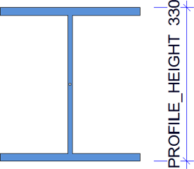
17
Beam height
PROFILE_HEIGHT
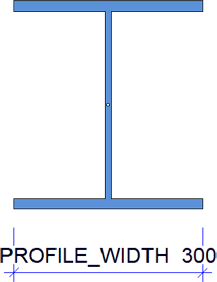
18
Beam width
PROFILE_WIDTH
19
Assembly height
ASSEMBLY_HEIGHT
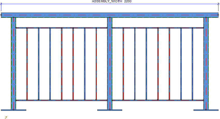
20
Assembly length
ASSEMBLY_WIDTH
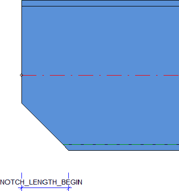
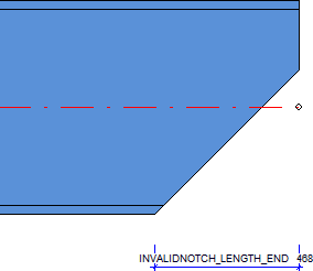
21
Notch length at start
NOTCH_LENGTH_BEGIN
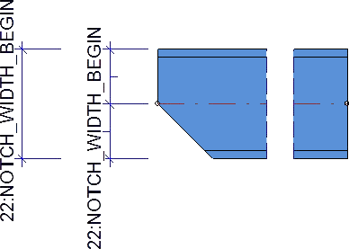
22
Notch length at start
NOTCH_WIDTH_BEGIN
23
Notch length at end
NOTCH_LENGTH_END
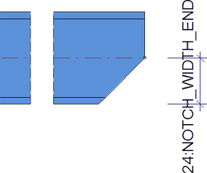
24
Notch width at end
NOTCH_WIDTH_END
26
Bores in front plates
BORES_IN_FRONT_PLATE
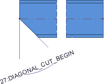
27
Oblique cut on beam at start
DIAGONAL_CUT_BEGIN
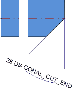
28
Oblique cut on beam at end
DIAGONAL_CUT_END
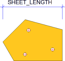
29
Sheet/plate length
SHEET_LENGTH
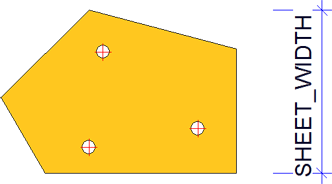
30
Sheet/plate width
SHEET_WIDTH
31
Sheet/plate thickness
SHEET_THICKNESS
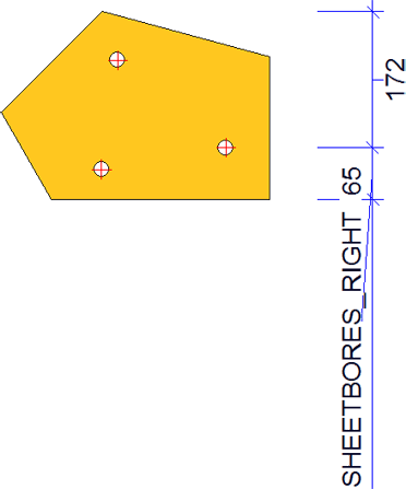
32
Bores in sheets/plates, right side
SHEETBORES_RIGHT
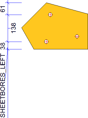
33
Bores in sheets/plates, left side
SHEETBORES_LEFT
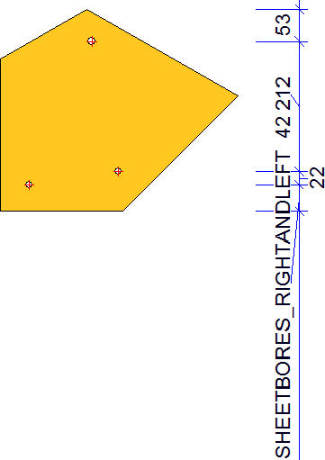
34
Bores in sheets/plates, right or left side
SHEETBORES_RIGHTANDLEFT
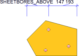
35
Bores in sheets/plates, upper half
SHEETBORES_ABOVE
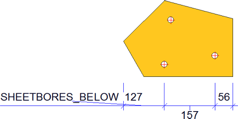
36
Bores in sheets/plates, lower half
SHEETBORES_BELOW
37
Bores in sheets/plates, upper or lower half
SHEETBORES_ABOVEANDBELOW
38
Outer contour of sheet/plate, right side
SHEETOUTLINE_RIGHT
39
Outer contour of sheet/plate, left side
SHEETOUTLINE_LEFT
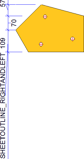
40
Outer contour of sheet/plate, right or left side
SHEETOUTLINE_RIGHTANDLEFT
41
Outer contour of sheet/plate, upper half
SHEETOUTLINE_ABOVE
42
Outer contour of sheet/plate, lower half
SHEETOUTLINE_BELOW
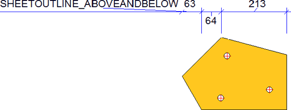
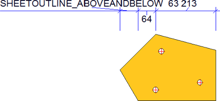
43
Outer contour of sheet/plate, upper or lower half
SHEETOUTLINE_ABOVEANDBELOW
44
Diameter of simple bores in main part
BORE_DIAMETER_MAINPART
45
Diameter of standard part bores in main part
NORMBORE_DIAMETER_MAINPART
46
Diameter of boltings in main part
CONNECTION_DIAMETER_MAINPART
47
Length of sheets/plates (sub-parts) in sectional views
SHEET_LENGTH_IN_SECT
48
Width of sheets/plates (sub-parts) in sectioanl views
SHEET_WIDTH_IN_SECT
49
Outer contour of sheets/plates, right and left side, in sectional views
SHEETOUTLINE_RIGHTANDLEFT_IN_SECT
50
Outer contour of sheets/plates (sub-parts), top and bottom side, in sectional views
SHEETOUTLINE_ABOVEANDBELOW_IN_SECT
51
Bores in sheets/plates (sub-parts), right or left side, in sectional views
SHEETBORES_RIGHTANDLEFT_IN_SECT
52
Bores in sheets/plates (sub-parts), top and bottom half, in sectional views
SHEETBORES_ABOVEANDBELOW_IN_SECT
53
Diameters of simple bores in sheets/plates (sub-parts) in sectional views
BORE_DIAMETER_IN_SECT
54
Diameter of standard part bores in sheets/plates (sub-parts) in sectional views
NORMBORE_DIAMETER_IN_SECT
55
Diameters of boltings in sheets/plates (sub-parts) in sectional views
CONNECTION_DIAMETER_IN_SECT
56
Position of sheet/plate, determined by one bore and the reference part
SHEET_POSITION_IN_SECT
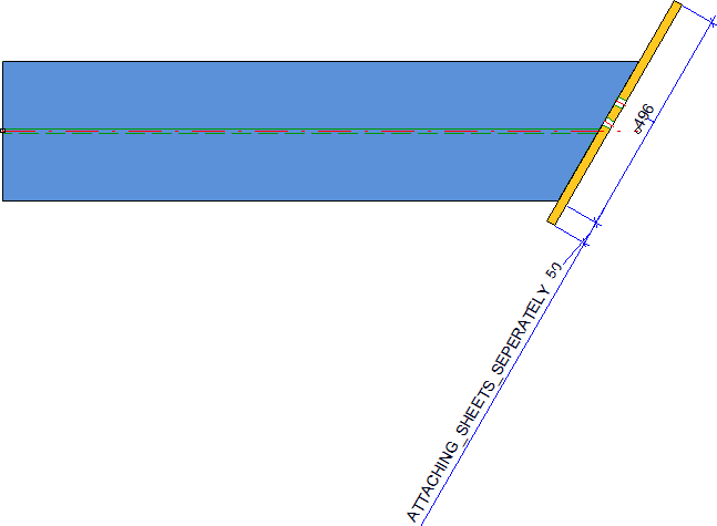
57
Attached plates, one chain dimension for each plate
ATTACHING_SHEETS_SEPERATELY
Via bores, if they are dimensioned perpendicular to screen plane and bores of sub-parts are dimensioned, or via outer contour; this is the only beam-related rule for which the direction VERTIKALSHEETAXIS is allowed in connection with the position INSIDE, in order to, e.g. dimension front plates on cuts in sheet/late direction!
58
Fillet radii on beam notches
PROFOUTLINE_RADIUS
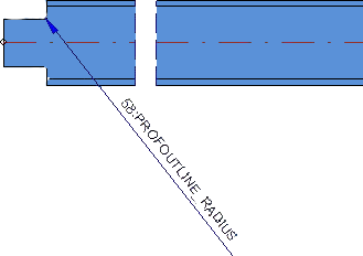
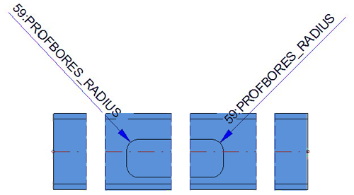
59
Fillet radii at material subtractions on beams/profiles
PROFBORES_RADIUS
60
Fillet radii on outer contours of sheets/plates
SHEETOUTLINE_RADIUS
61
Fillet radii on material subtractions on sheets/plates
SHEETBORES_RADIUS
62
Fillet radii on outer contours of sheets/plates in sectional views
SHEETOUTLINE_RADIUS_IN_SECT
63
Fillet radii on material subtractions on sheets/plates in sectional views
SHEETBORES_RADIUS_IN_SECT
64
Length of cut at beam/profile start
SECTION_LENGTH_BEGIN
65
Length of cut at beam/profile end
SECTION_LENGTH_END
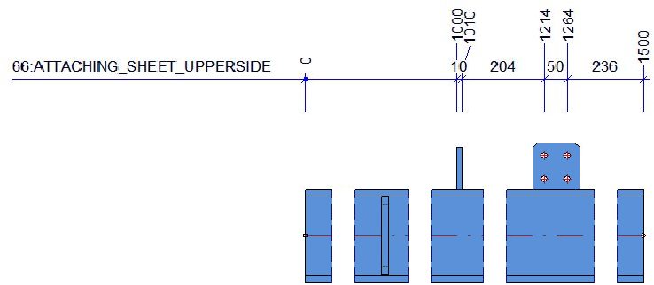
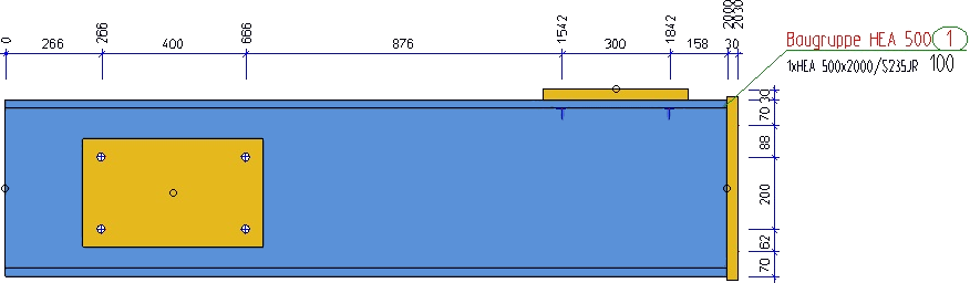
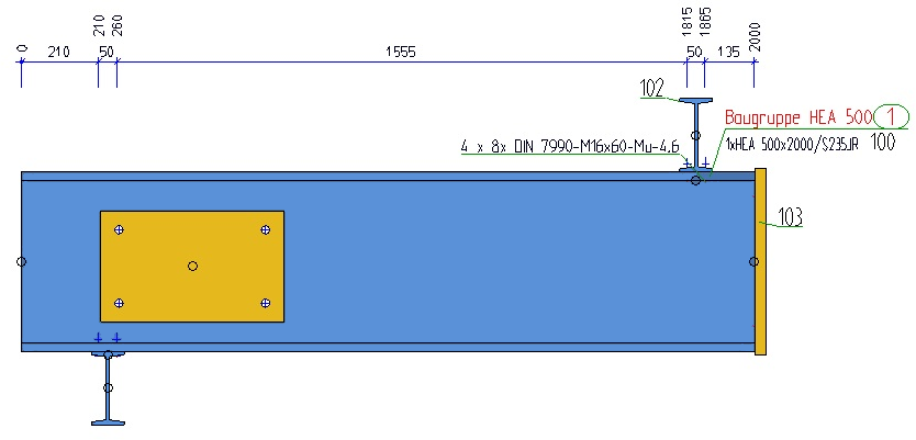
66*
Attached plates on top side of beam, via bores or outer contour
ATTACHING_SHEET_UPPERSIDE
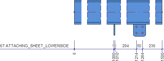
67*
Attached plates on bottom side of beam, via bores or outer contour
ATTACHING_SHEET_LOWERSIDE
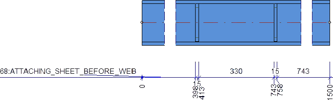
68*
Attached plates on web surface, in front of web, via bores or outer contour
ATTACHING_SHEET_BEFORE_WEB
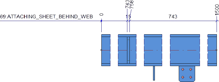
69*
Attached plates on web surface, behind web, via bores or outer contour
ATTACHING_SHEET_BEHIND_WEB
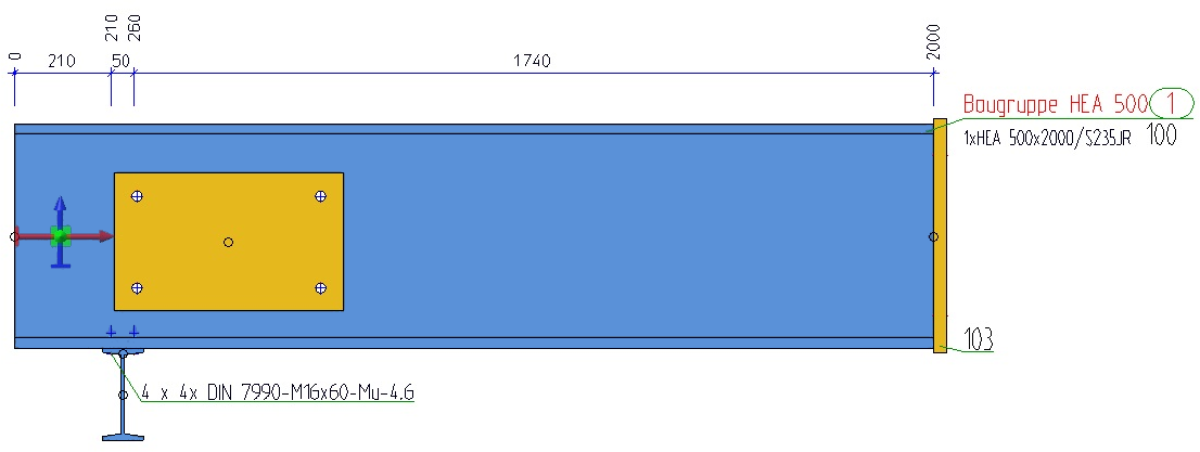
70*
Attached beams/profiles with axis, to main part axis, dimension via system axis
ATTACHING_PROFILES_VERT
71
Sub-system in upper flange area
SUBSYSTEM_UPPERFLANGE
Only grid and sub-grid lines, but no parts will be dimensioned!
72
Sub-system in lower flange area
SUBSYSTEM_LOWERFLANGE
Only grid and sub-grid lines, but no parts will be dimensioned!
73
Sub-system in web area
SUBSYSTEM_WEBFACE
Only grid and sub-grid lines, but no parts will be dimensioned!
74
Sub-system in upper flange and lower flange area
SUBSYSTEM_FLANGES
Only grid and sub-grid lines, but no parts will be dimensioned!
75
Sub-system in upper flange, lower flange and web area
SUBSYSTEM_WEB_AND_FLANGES
Only grid and sub-grid lines, but no parts will be dimensioned!
76
Length of beam sub-parts
PROFILELENGTH_ATTACHING_PROFILES
Sub-part lengths of all (also oblique) sub-parts
77
Connected beam sub-parts
CONNECTED_PROFILES
Start and end of all direct connections of sub-parts to main part
80
Connected sub-part beams on relevant beams
CONNECTED_PROFILES_RELEVANTPROFILES
Start and end of all direct connections of sub-parts to relevant parts
83
Attached plates with bores, incl. bore in side view
ATTACHING_SHEETS_VERT
84
Bores in sub-parts (bores of all sub-parts) incl. bores + viewing direction
SUBPARTBORES_VERT
85
Beam processing in web, incl. processings in side view
PROFBORES_INWEB_VERT
86
Beam processings in upper flange, incl. processings in side view
PROFBORES_INUPPERFLANGE_VERT
87
Beam processings in lower flange, incl. processings in side view
PROFBORES_INLOWERFLANGE_VERT
88
Beam processings in upper and lower flange, incl. processings in side view
PROFBORES_INFLANGES_VERT
89
All parts via bore
ALL_PARTS_BORES
Especially for framework constructions (Assembly with or without main part):
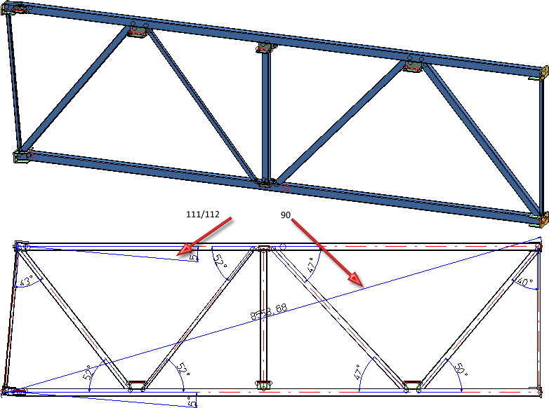
90
Diagonal total dimensions of an assembly
TOTAL_SIZE_ASSEMBLY
Especially for framework constructions (assembly without main part)
94*
All attached parts of relevant beam sub-parts, via outer contour
ATTACHING_PARTS_RELVPROFS
96*
Attached Sheet Metal parts with bores on relevant beam sub-parts
ATTACHING_SHEETS_RELVPROFS
98
Bores in web of relevant beam sub-parts
PROFBORES_INWEB_RELVPROFS
99
Bores in upper flange of relevant beam sub-parts
PROFBORES_INUPPERFLANGE_RELVPROFS
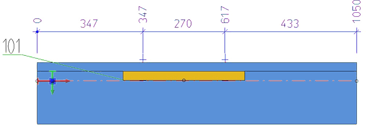
100
Bores in lower flanges of relevant beam sub-parts
PROFBORES_INLOWERFLANG_RELVPROFS
101
Bores in flanges of relevant beam sub-parts
PROFBORES_INFLANGES_RELVPROFS
105
Attached plates/sheets on relevant beam sub-parts; one dimension chain for each plate/sheet
ATTACHING_SHEETS_SEPERATELY_RELVPROFS
106
Attached plates/sheets on upper beam sides on relevant beam sub-parts; via bores or outer contour
ATTACHING_SHEET_UPPERSIDE_RELVPROFS
107
ATTACHING_SHEET_LOWERSIDE_RELVPROFS
108
Attached plates/sheets on web surface on relevant beam sub-parts, before web, via bores or outer contour
ATTACHING_SHEET_BEFORE_WEB_RELVPROFS
109
Attached plates/sheets on web surface on relevant beam sub-parts, after web, via bores or outer contour
ATTACHING_SHEET_BEHIND_WEB_RELVPROFS
110*
Attached parts on relevant beam sub parts
ATTACHING_PROFILES_VERT_RELVPROFS
111
Angle between beam main part and connected sub-part beams
STWDimRuleIdent_ANGLE_CONNECTED_PROFILES
112
Angle between relevant beams and connected sub-part beams
STWDimRuleIdent_ANGLE_CONNECTED_PROFILES_RELPROFS
113*
Beam sub-parts, not vertical to main part axis
ATTACHING_PROFILES_INUPPERFLANGE
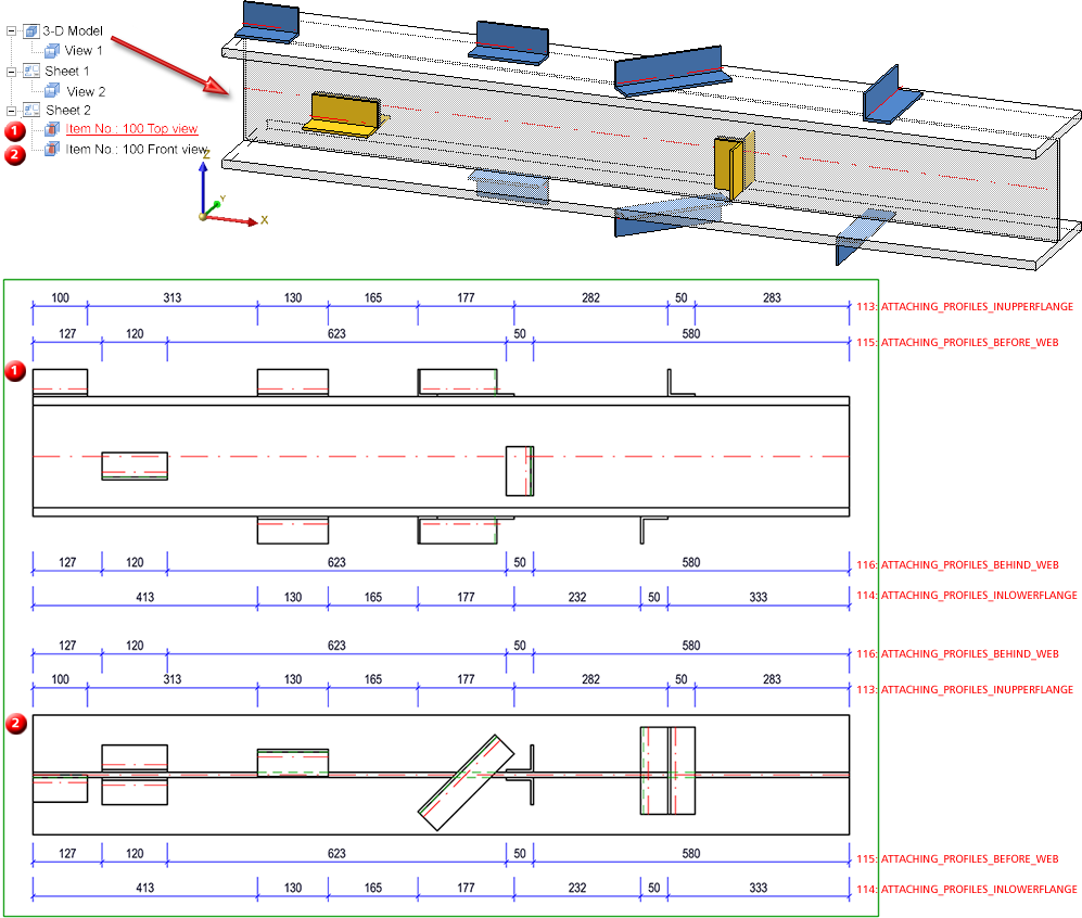
114*
Beam sub-parts on lower flange, not vertical to main part axis
ATTACHING_PROFILES_INLOWERFLANGE
115*
Beam sub-parts in front of web, not vertical to main part axis
ATTACHING_PROFILES_BEFORE_WEB
116*
Beam sub-parts behind web, not vertical to main part axis
ATTACHING_PROFILES_BEHIND_WEB
117*
Beam sub-parts, not vertical to main part axis
ATTACHING_PROFILES
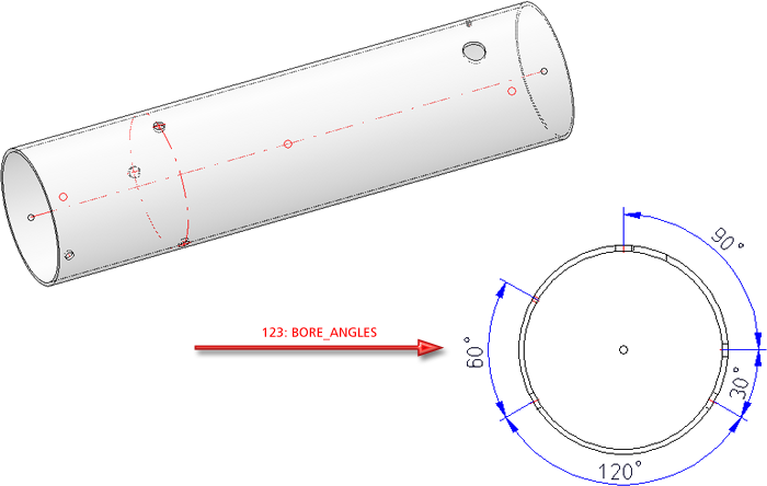
123
Angle between bore axes
BORE_ANGLES
(only in view from left and right and only parallel to screen plane!)
124
Beam processings of the type Slot
PROF_LONGHOLES_ONLY
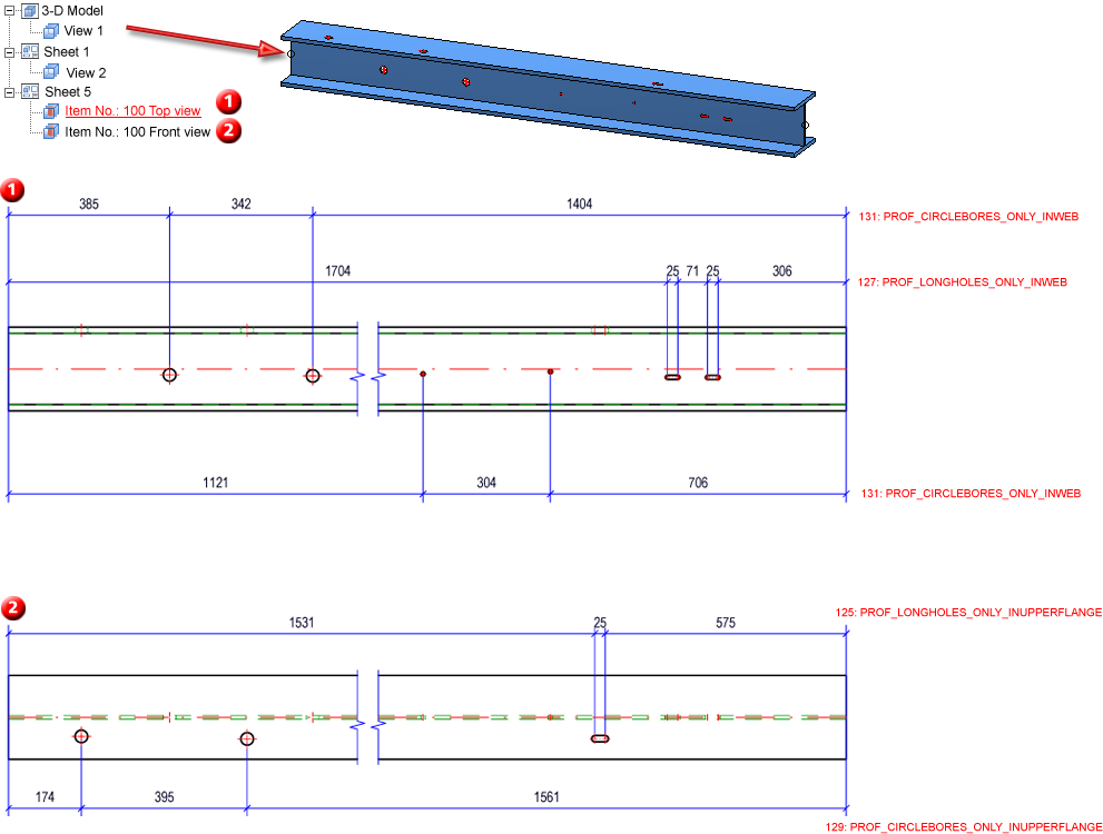
125
Beam processings of the type Slot in upper flange
PROF_LONGHOLES_ONLY_INUPPERFLANGE
126
Beam processings of the type Slot in lower flange
PROF_LONGHOLES_ONLY_INLOWERFLANGE
127
Beam processings of the type Slot in web
PROF_LONGHOLES_ONLY_INWEB
128
Beam processings of the type Circular bore
PROF_CIRCLEBORES_ONLY
129
Beam processings of the type Circular bore in upper flange
PROF_CIRCLEBORES_ONLY_INUPPERFLANGE
130
Beam processings of the type Circular bore in lower flange
PROF_CIRCLEBORES_ONLY_INLOWERFLANGE
131
Beam processings of the type Circular bore in web
PROF_CIRCLEBORES_ONLY_INWEB
132
Sheet length
SHEETMETAL_LENGTH
133
Sheet width
SHEETMETAL_WIDTH
134
Sheet height
135
Parametric linear dimensions of sheets
SHEETMETAL_PARA_DISTANCE
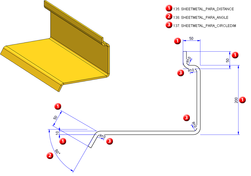
136
Parametric angular dimensions of sheets
SHEETMETAL_PARA_ANGLE
137
Parametric circular dimensions of sheets
SHEETMETAL_PARA_CIRCLEDIM
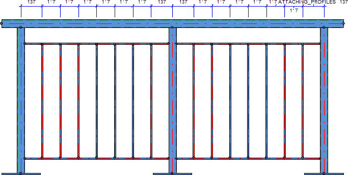
Especially for Railings
1001
Total length of Railing segment assembly
TOTAL_LENGTH_RAILINGSEGMENT
only for Railing segment assembly:
1002
Total height of Railing segment assembly
TOTAL_HEIGHT_RAILINGSEGMENT
only for Railing segment assembly:
1003
Total length of Railing segment assembly w/o base plates
TOTAL_LENGTH_RAILINGSEG_WITHOUT
only for Railing segment assembly:
1004
Total height of Railing segment assembly w/o base plates
TOTAL_HEIGHT_RAILINGSEG_WITHOUT
only for Railing segment assembly:
1005
Total dimension of Railing segment assembly
TOTAL_SIZE_RAILINGSEGMENT
only for Railing segment assembly:
1006
Clear distances between posts
CLEARANCE_POST
only for Railing segment assembly:
1007
Distances between post axes
CENTERDISTANCE_POST
only for Railing segment assembly:
1008
Clear distances between rods
CLEARANCE_WEBMEMBER
only for Railing segment assembly:
1009
Distances between rod axes
CENTERDISTANCE_WEBMEMBER
only for Railing segment assembly:
1010
Hand rail excess length
HANDRAIL_PROJECTION
only for Railing segment assembly:
1011
Sub-parts
RAILING_SUBPARTS
only for Railing segment assembly:
1012
Sub-parts, Post assembly
POST_SUBPARTS
only for Railing segment assembly:
1013
Sub-parts, Infill assembly
FILLING_SUBPARTS
only for Railing segment assembly:
1014
Angle Post - Handrail
ANGLE_POST_HANDRAIL
only for Railing segment assembly:
1015
Bores
RAILING_BORES
only for Railing segment assembly: