"Civil Engineering functions" docking window > Steel Engineering > Connections > Front side to web/flange side > Flange > Stabilizing pipe
Use this Design Variant-based function to insert a stabilizing pipe connection between two beams or profiles. Possible beams or profiles are I-beams, U-beams and hollow profiles.
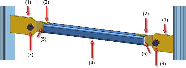
The connection consists of

The plates on the beam including the weld seams are assigned to the assembly of the respective beam or profile. All other components of the generated stabilizing pipe connection and their weld seams will be combined into one assembly with the name Stabilizing pipe.
After calling the function, proceed as follows:
Configurations for stabilizing pipe connections can be saved, which enables you to access your individual configurations at any time afterwards.
The configuration of the stabilizing pipe connection takes place via the tabs of the dialogue window.
Selected parts
This tab provides information about the previously identified beams, e.g. designation, material, dimensions etc. Value inputs are not possible here.
Connection
On this tab you specify the dimensions for the stabilizing pipe connection.
Required dimensions are:
The dimensions:
The stabilizing pipe can be placed either to the right or to the left of the plate on the beam. If you want to rotate the connection 90 degrees, activate the corresponding checkbox.
Plates
On this tab you can specify the size of the plates on the beam and on the stabilizing pipe, i.e. their height and width and, if desired, the type of corner processing for the plates. Possible are chamfers, internal or external fillets. Depending on the type of corner processing, enter the fillet radius or the chamfer length.
(1) Plate on beam, (2) Plate on pipe, (3) Cover plate, (4) Distance of cover plate
If a cover plate for the stabilizing pipe is to be created, activate the Create checkbox and enter the distance to the stabilizing pipe. Select the option for the fillet and enter the distance to the pipe. You select the option for the fillet from the listbox. Possible are:
Standard parts
On this tab you specify the type and material of the connection components .
Click the  icon and select the desired component from the catalogue.
Weld seams
On this tab you specify whether weld seams are to be created for the plates on the beam, the plates on the pipe and the cover plates. If you want the weld seams to be created, activate the corresponding checkbox and enter the seam thickness.
Click the Preview button if you want to display a preview of the connection based on the currently entered data. If you want to modify the current data, apply the required changes and click Preview again to update the preview. Click OK to insert the connection according to the current data and close the dialogue window. If you click the Cancel button, the window will be closed, and the specified or changed connection will not be inserted.
Related Topics
Connections + Variants (3-D SE) • Dialogue Window for Connections - Type I (3-D SE) • The Catalogue System for Connections + Variants (3-D SE)
|
Version 2102 - HiCAD Steel Engineering | Date: 15/11/2016 | © Copyright 1994-2016, ISD Software und Systeme GmbH |