Use this interface to prepare HiCAD data for the export to NC machines. It depends on the machine type whether the DSTV-NC interface or the NCX interface will be selected.
![]() Please note that only itemised parts will be exported.
Please note that only itemised parts will be exported.
To export a file via the NCX interface, select  >
>  Save as > Further... >
 NCX . The NCX Interface dialogue window will be displayed.
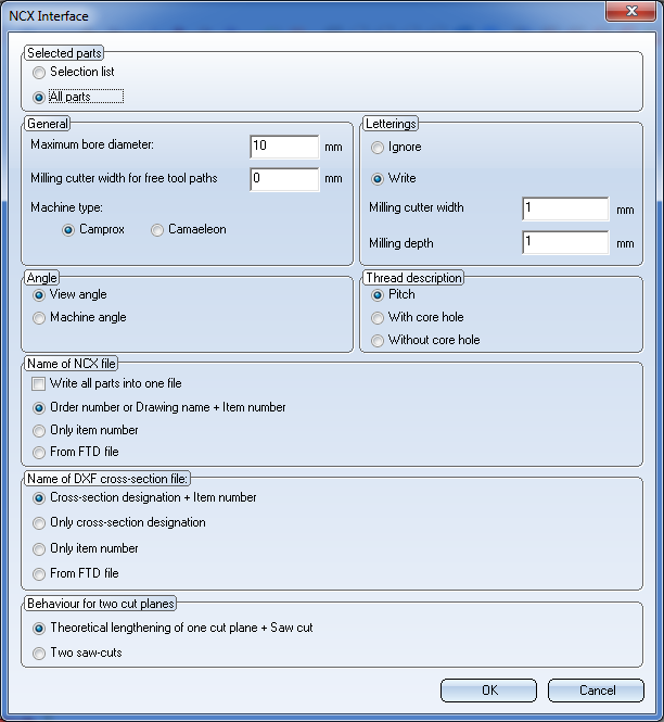
Beneath Selected parts you can specify to which parts the export is to be applied. If you chose All parts, the entire Steel Engineering drawing will be exported; if you choose Selection list, only the currently selected part(s) will be exported. The parts to be exported must be Steel Engineering parts!
In the General area you can specify a Maximum bore diameter(Default: 10 mm) and a Milling cutter width for free tool paths. Free tool paths are all material subtractions that are no bores, no slots or (filleted) rectangular subtractions.
Use the Camprox or Camaeleon radio buttons to select the NC software for the export. The differences between these two settings are as follows:
For saw cuts, the variable WW1 is always initialized with the value 1 ("Orientation: running to the right") if Camprox has been selected; if Camaeleon has been chosen, the init value can also be -1 ("Orientation: running to the left").
Furthermore, there are differences concerning the processing of countersunk holes:
Beneath Letterings, set Ignore if you do not want them to be exported. If you selected Write to include the letterings in the export, you need to specify the corresponding dimensions in the Milling cutter width and Milling depth fields.
By default, these values are both set to 1. In this case it is recommended to use the "HiCAD - ANSI_KON" font and a font size of 10 in the text input tool for the lettering, a setting that has been successfully used in practice. The HiCAD - ANSI_KON font requires only few edges per letter. The font size 10 guarantees for a milling cutter width and a milling depth of 1 that all letters will actually be created during milling. Other, untested fonts and smaller sizes may probable not lead to the desired result.
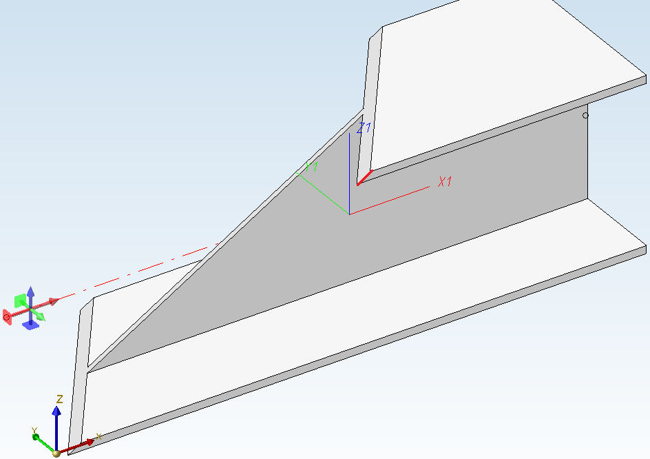
Beneath Angle you can choose between an export of the View angle or the Machine angle.
If you choose View angle, the angle between the local X-axis and the section line of top surface and lateral surface of the beam will be output. (red dash-dotted line in the image below).
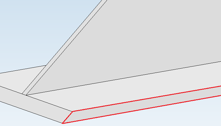
If you select Machine angle, the "lateral" angle between the top surface and the base surface of the beam will be output (highlighted in red in the image below). This setting is of importance for diagonally cut beams, as these beams have angle dimensions with different values.
Beneath Thread description you can select whether the thread is to be interpreted as a Pitch (which makes sense if you work with the Camprox machine type), With core hole or Without core hole.
Beneath Name of NCX file you can specify whether the file is to be saved with the Order number or Drawing name + Item number in the file name, or Only with the item number.
You have the additional From FTD file option to use the parameters for name assignment set in the system file NCW_Dateibezeichnung.ftd.
The NCX interface then creates for each part an NC file with the file extension .NCW, and for beams additionally a DXF file with the beam cross-section.
The name configuration is omitted if you activate the Write all parts into one file checkbox in the General area, instead of creating one file for each part.
In this case, you only need to select the automatically generated Name of DXF cross-section file (beam designation):
If you choose the From FTD file option, the name will be created as set in the system file NCW_Profilbezeichnung.ftd. Here it is important that attributes defined in the FTD file have been appropriately assigned in the drawing for export.
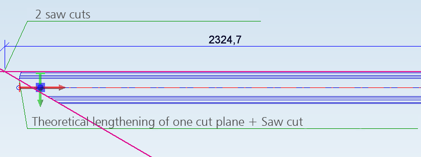
If two cut planes exist on the beam, you have the following two output options beneath Behaviour for two cut planes:
The image below shows the difference:
After export, a log file will be shown, listing information and possible errors that occurred during data transfer. Double-click a log entry to view further information.
![]() Please note:
Please note:
![]()
Related Topics
DTSV Product Interface • DSTV BOM Interface • Steel Engineering Interfaces
|
Version 2102 - HiCAD Interfaces | Date: 15/11/2016 | © Copyright 1994-2016, ISD Software und Systeme GmbH |