One special thing about the functionality of the 3-D Metal Engineering grid is the fact that you are enabled to place the required elements of a glazing construction, with only a few mouse-clicks, into a pre-fabricated facade contour made up of connected sketches.
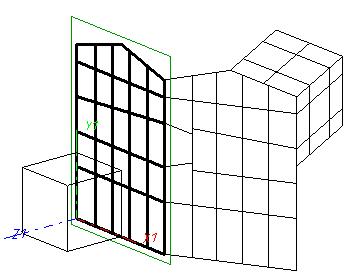
Example of a 3-D Metal Engineering grid
 The sketches in which you draw your contour need to be placed below the Grid (assembly) entry in the ICN part structure.
To insert mullions and transoms in the drawing you can, after activating the appropriate function in the Metal Engineering grid menu (e.g. Transom, via LogiKal, or Mullion, from drawing) mark the geometry elements in the grid to which you want to assign the part.
For the insertion of Mullions (vertical members) and Transoms (horizontal members) you have the following three fitting options:
If you click a line while holding down the SHIFT key, all parallels to this line are detected and highlighted together with the selected line. You can also select several lines individually by holding down the CTRL key and clicking the required lines one after the other. The previously selected mullion and transom model is then assigned to the selected lines.
An extended Plugin enabling a semi-automated working with the Metal Engineering Grid is available via Settings  > Plugins > Metal Construction.

Related Topics
New Grid Assembly • 3-D Metal Engineering Grid • Add Mullions/Transoms to the HiCAD Catalogue
|
Version 2102 - HiCAD Metal Engineering | Date: 15/11/2016 | © Copyright 1994-2016, ISD Software und Systeme GmbH |