
The bend areas for sheet construction are modelled as approximated cylinder segments. During development, the individual segments are transformed to a plane and assigned additional stretching. This is to allow material elongation to be taken into account in partially plastic bending. HiCAD also provides the empirical allowance methods standard in practice.
A particular calculation method is represented by means of a system file. These files are prepared as examples, but in practice each user will store one or more of his own methods in this way. Before developing, you can select the system file via Sheet Metal > Sheet development > Parameters > New, Parameters.
You can enter the method, which is automatically activated (e.g. DIN6935.DAT) once the system starts, in the system file .../makroabw/ABWPAR.DAT.
Several basic types of calculation method have been prepared. The user will choose one of these types and specify it by setting the parameters to company-specific values. The basic structure of these files, however, is the same. It is divided into comment, type ID and table.
The following allowance methods are avilable:
![]()
Example:
#
------------------------------------------------------------------------------
# H i C A D - Sheet Development
# DIN6935_.FKD Factor File
# ------------------------------------------------------------------------------
#
# This file contains the factors for calculating the change in length
# according to DIN_6935, a factor method.
#
# -> Column 1: Internal radius/sheet thickness ratio up to which the
following holds:
# <- Column 2: Position of the neutral fibre, middle=1, internal=0
# Column 3: To be set to zero
# Column 4: To
be set to zero
F DIN 6935
0.651 0.600 +0.000 -0.000
1.001 0.600 +0.000 -0.000
1.501 0.700 +0.000 -0.000
2.401 0.800 +0.000 -0.000
3.801 0.900 +0.000 -0.000
999.000 1.000 +0.000 -0.000
Lines in the comment area must begin with #. After this block comes a line the initial letter of which characterises the type of method. A description of the method then follows. The following types have been implemented up to now:
|
F |
Factor Method, e.g. DIN6935 |
F determines the stretched length across the neutral fibre, which is corrected in the direction of the arc interior for small radii. Factor 1 means an arc length on the neutral fibre, while factor 0 reflects the arc length on the interior. |
|
Z |
The Standard Allowance Methods with External Reference Lengths, e.g. Heuschen, also Dubbel |
Z is the most frequently used method. The reference lengths for an obtuse angle are the imaginary intersection points of the sides on the flange exterior; in the case of acute angles, the reference dimension is formed via the tangent perpendicular to the dimension direction. This corresponds to the practical measurement of a workpiece using the calliper gauge. The stretched length is then the sum of the lengths determined in this way plus the allowance values per bend. |
|
I |
A Modified Allowance Method with Internal Reference Lengths, e.g. Kaiser |
I is similar to Z, the difference being that it is not the exterior, but the interiors of the sides that define the reference lengths. The practical significance of this method is that the user often sets all allowances to zero and obtains a simple method with acceptable calculation results for appropriate bend radii. |
|
H |
A Modified Allowance Method with Interpolation, e.g. Haemmerle |
H is similar to Z, with two modifications: First, the intersection points of the sides bound the reference line here even for angles above 90 degrees. Second, the allowance value is interpolated linearly in the interval of the angles. |
|
|
Polyhedral Developments |
The above explanations apply only to genuine sheet developments, but not to polyhedral developments. In these cases, only the existing surfaces are transformed to the plane if INT/thickness = 1000. If a thickness <1000 is specified, the stretched length resulting from the geometric middle of the specified imaginary thickness is shortened. |
There follows a four-column, format-bound table the respective interval limits of which need to be completed with 999.000. Only 2 columns are of relevance to method F, but all four columns are otherwise relevant.
The columns have the following meaning for allowance methods:
|
# -> Column 1 |
Interval for the inclusive sheet thickness |
|
# -> Column 2 |
Inclusive bend angle |
|
# -> Column 3 |
Inclusive internal radii |
|
# <- Column 4 |
Correction summand in mm (usually less than zero) |
Examples:
|
DIN6935.dat |
This file contains the factors for calculating the change in length for developments, as per DIN6935.
|
|
Aurora.dat |
This file contains the values which are added to the external dimensions of the leg lengths during development. This allowance method is used at the company AURORA. |
|
Kaiser.dat |
This file contains the values which are added to the internal dimensions of the leg lengths during development. This allowance method is used at the company KAISER. |
 In order to display the allowance method in the bend zone of the blank, you need to modify the relevant setting in the ABWPAR.DAT file as follows:
Abwicklungsverfahren auf Schicht an 2D-Abwicklung ( -1: kein Eintrag, 0...999 -> Schichtnummer )
1
[Development method on layer for 2-D development (-1:no entry, 0.999-> layer number)]
1
If no allowance method has been defined, enter NONE.
![]()
The CHAMFER allowance method has been developed to match the requirements of the Puzzle piece Design Variant.
Before insertion of the variant, the CHAMFER allowance method must be selected for the Sheet Metal part. Proceed as follows:
 .
. With allowance checkbox to ensure that the allowance method will be considered.
![]()
The allowance method ACP is available for Aluminium Composite Panel blanks. Development and milling dimensions are derived from the 3-D drawing dimensions. Per edge, the corresponding linear dimension will be subtracted from the final dimension. The sum of the milling dimensions equals the blank dimensions.
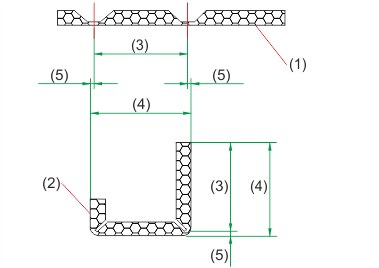
(1) Section through blank for bending simulation
(2) Section through the sheet metal part of an aluminium composite panel
(3) Milling dimension
(4) Final dimension
(5) Subtracted linear dimension per edge
![]()
Alminium composite panels can, for instance, consist of two 0,5 mm aluminium cover sheets with a mineral core. In HiCAD the plate is represented simplified as a one-layer sheet. Since the weight calculation is done based on a homogeneous material, an own material is assigned to the panel.
The file ACP.ABW is used for the allowance method for composite panels. In exceptional cases, for bent sheets with outside millings, you can use the allowance method ACP_outside.ABW instead.
Bend radius (BRAD): 0.01 (Standard, for inside millings)
Bend radius, milled outside (BRAD_OUT): 1.50 (Exception, for outside millings)
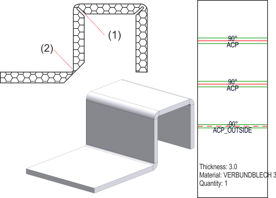
(1) Inside milling
(2) Outside milling
![]()
Related Topics
New/Change Technology Parameters • Blank Parameters
|
Version 2102 - HiCAD Sheet Metal | Date: 15/11/2016 | © Copyright 1994-2016, ISD Software und Systeme GmbH |