Change Drawing Frame - Preparation
The supplied templates for drawing frames are 2-D parts that are stored
in the HiCAD drawing directory:
- DINA0.FIG / DINA0_TS.FIG for DIN A0
- DINA1.FIG / DINA1_TS.FIG for DIN A1
- DINA2.FIG / DINA2_TS.FIG for DIN A2
- DINA3.FIG / DINA3_TS.FIG
for DIN A3
- DINA4Q.FIG / DINA4Q_TS.FIG for DIN A4 landscape
- DINA4H.FIG / DINA4H_TS.FIG for DIN A4 portrait
The frames ending on _TS contain the title blocks for the HELiOS master
part attributes.
Before changing a drawing frame, check -
if you do not know - the directory in which your drawings are stored by
default:
- Select
 > Settings.
- Open the
Directories folder.
- The path specified
behind C: in the 4th line is the current drawing directory. You will need
this directory later when saving the title block.
Now proceed as follows:
- Create a new
drawing on a 1:1 scale.
- Load the drawing
frame to be changed, e.g. DINA4H (A4 portrait). To do this, right-click
the drawing surface and, in the context menu, choose the Insert, Drawing frames function.
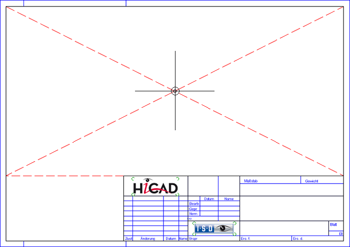
- A preview image of the drawing frame will be displayed, a HiCAD will prompt you to specify the position of the frame in the drawing. The fitting point of the frame in the drawing is the intersection point of the diagonals above the title block.

- Important: The position of the fitting point must be located in the coordinate origin (A 0 0)!
- Drawing frames
are "auxiliary drawing parts" and are not normally displayed in the
ICN. Should the drawing frame therefore not appear in the 2-D
tab of the ICN, right-click the name of the drawing in the ICN, choose Auxiliary part On/off in the context menu and then
choose ON. This then displays the
drawing frame in the 2-D part structure.

Related Topics
Auxiliary
Objects in the ICN • Predefining Directories
|
Version 2102 - HiCAD Basics | Date: 15/11/2016 | © Copyright 1994-2016,
ISD Software und Systeme GmbH
|
Feedback on this topic
|
 > Settings.
  > Settings.