Plant Engineering > Isometry / Pipe Spool Drawing > Isometry settings 
Plant Engineering > Isometry / Pipe Spool Drawing > Pipe spool drawing settings 
Isometry+Pipe Spool Drawing > Settings 
 The following description refers to isometries and pipe spool drawings.
The positioning of certain 2-D isometry drawing elements in a drawing frame can be preset in the 2-D Drawing elements tab. Furthermore, you can pre-set the position of some elements in the drawing frame, such as the north arrow or lists. In addition, it is possible to include and position arbitrary 2-D drawing supplements existing as FIG files.
|
Contents |
|
|
(1) |
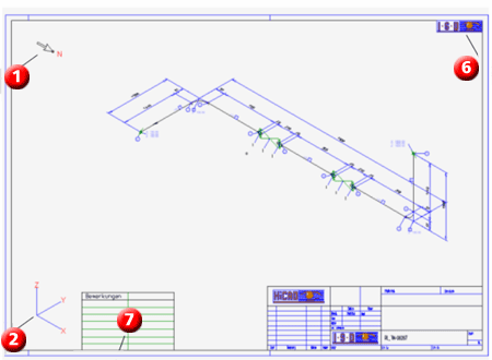
North arrow |
|
(2) |
Tripod |
|
(3) |
Bill of materials |
|
(4) |
Length list |
|
(5) |
Connection list |
|
(6) |
LOGOISD.FIG |
|
(7) |
TEXTTAB1.FIG |
The elements north arrow, tripod and the three list types cannot be removed from this table. If they actually appear in the isometry depends on whether they are activated in the isometry dialogue.
FIG files can be entered and removed. If a file has been entered, the associated graphic appears in the isometry after its generation.
Meaning of the columns
The „right“ or „left“ positioning options place elements near the right/left frame border, one after the other, from top to bottom. The positioning options "top" and "bottom" place the elements near the top/bottom frames, one after the other, from left to right. User -defined elements (company logos etc.) are always inserted last.
The settings shown above are reflected in the sheet configuration as follows(the lists 3-5 have not been activated in the isometry dialogue):

Default
Use the Default button to create a simple "empty" pre-setting, containing only the elements North arrow, Tripod and the three list types.
Related Topics
Settings (PE/Iso) • Isometry and Pipe Spool Drawing (PE/Iso) • Isometry/Pipe Spool Drawing Functions for the Layout Plan (PE)
|
Version 2102 - HiCAD Plant Engineering | Date: 15/11/2016 | © Copyright 1994-2016, ISD Software und Systeme GmbH |