
Project: HiCAD Interfaces
Drawing > New/Open > Open  > 3-D Import
IFC files (IFC2x3 or IFC4) are opened in HiCAD by calling the function 3-D Import and then selecting the corresponding *.ifc or ifczip file.
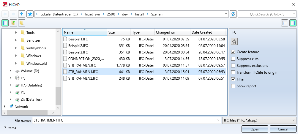
On the right side of the dialogue window, you can set Options for import by activating/deactivating the checkboxes.
Click Open to close the dialogue window and start the import of the currently selected objects. If you click Cancel, the dialogue window is closed and the import is cancelled.
Please note:
You define which IFC attributes are assigned to which HiCAD attributes in the Configuration Editor at Interfaces > IFC via the parameter Attribute mapping configuration. This is available for both import and export.
![]() Please note:
Please note:
When importing IFC files, the BOM relevance of parts and assemblies will be automatically removed.
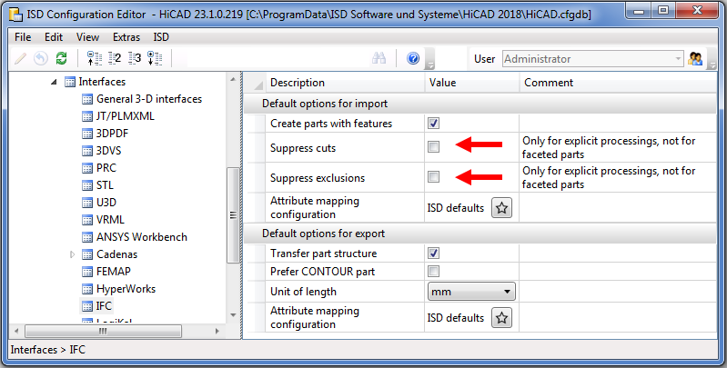
The default settings in the dialogue window as well as other parameters can be defined in the Configuration Editor at Interfaces > IFC.
Settings made in the dialogue window for an interface format can be saved as favourites. To do this, click on the  symbol in the dialogue window. You can find more information on favourites management in the in the Manage Favourites topic of the HiCAD Basics Help. You can specify which favourite is used as the default in the import dialogue in the Configuration Editor at Interfaces > Import.
Clear this checkbox if you do not want feature data to be saved in HiCAD after import. During IFC import, parts are generated using feature calculation. If the checkbox is inactive, this feature data is discarded. This can be useful for complex designs, since feature data can impair performance.
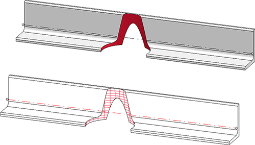
You can suppress processings when importing IFC files. This is possible for
 Please note that the suppression only applies to explicit mechanical processings and not to faceted parts. For example, the processing shown in the figure is always imported.
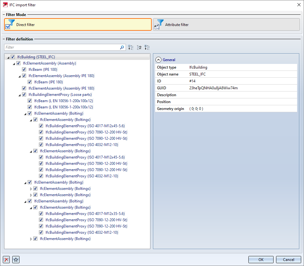
If the Filter option is active, the IFC import filter dialogue window is called after clicking Open. Here you can filter the objects for the import.
If the checkbox is active, IfcSite (topmost element, including sub-elements) is transformed to the origin. The original coordinate system is saved as an installation coordinate system called IfcSite in the feature of the IfcSite assembly.
If the Show report checkbox is active, a report with errors, warnings and further information is displayed after the import.
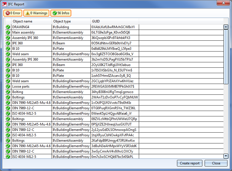
By clicking on an entry in the report, further information about the object is displayed. By clicking on the Create report button, the report can be saved as a CSV file..
If the Filter option is active, the IFC import filter dialogue window is displayed after clicking Open. Here you can restrict the parts to be imported by specifying direct filters or attribute filters.
Please note:
You can use either direct filters or attribute filters. A combination of direct and attribute filters is not possible.
In this mode, you can select objects to be excluded from import by activating the corresponding checkboxes in the tree structure. HiCAD also supports multiple selection with the CTRL and SHIFT keys.
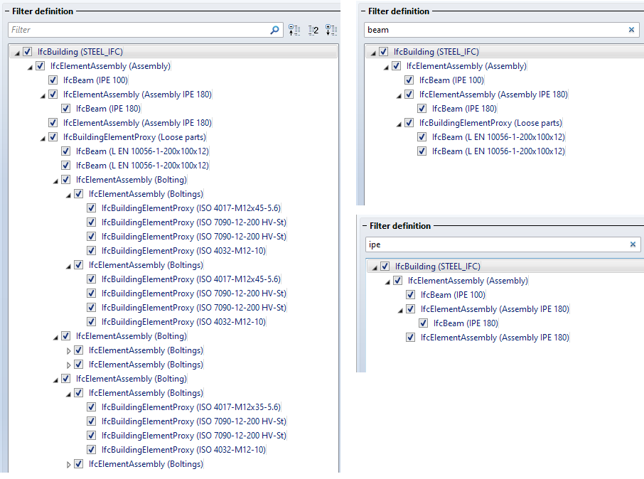
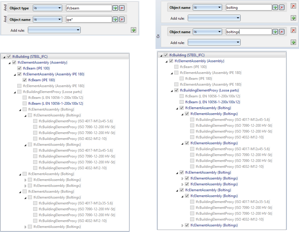
In addition, you can enter a string at the top of the dialogue window, according to which the import is to be filtered. This can be any sub-string of the IFC name or IFC type. Example, for example beam. The tree structure is adjusted immediately. If you then enter another sub-string, the tree structure is filtered further.
In the following example, the partial string beam was specified first and then ipe.
Clicking on  in the input field removes the filter again.
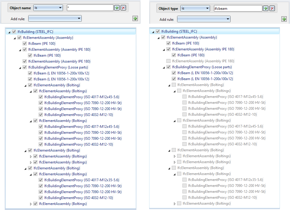
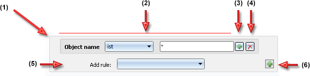
Instead of direct filters, attribute filters can also be used. Here you can filter the structure according to the attributes Object name, Object type, Designation and GUID. Several filter criteria can be combined with AND or OR.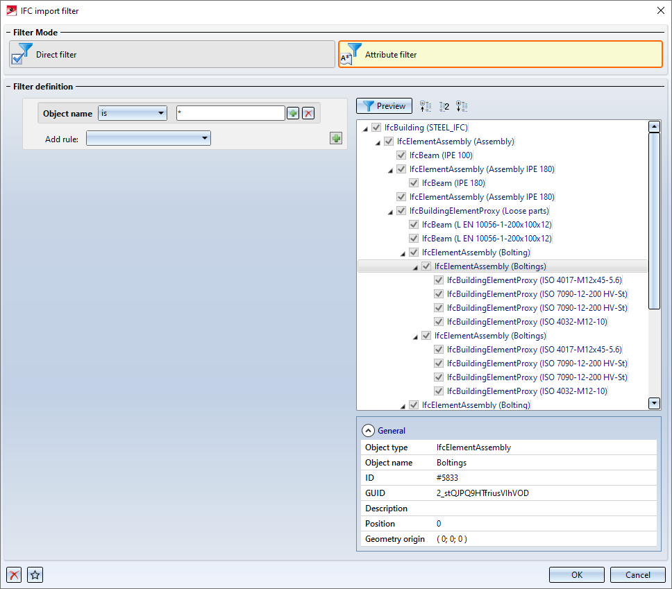
|
|
(1) |
|
Rule block |
|
(2) |
|
Rule V |
|
|
(3) |
|
Add OR rule to current rule block |
|
|
(4) |
|
Remove rule / rule block |
|
|
(5) |
|
Add AND rule to current rule block |
|
|
(6) |
|
Add new OR rule block If you click on the symbol holding down the CTRL key, the rule block is copied. If several rule blocks exist, you can delete control blocks with a click on the |
Attribute filters can consist of one or more rule blocks, each rule block being identified by a grey rounded rectangle (1). A rule block consists of one or more rules, which can be linked by AND or OR. Each rule (2) contains the attribute to be filtered by and the condition it must fulfill. This condition consists of an operator and a string, where the operators here are and are not allowed. The string can contain the wildcards *, ? and \.
|
Wildcard |
Function |
Example |
|---|---|---|
| * |
Placeholder for any number of characters |
All (*), starts with Prof (Prof*), contains Prof (*Prof*), ends with Prof (*Prof) |
|
? |
Placeholder for exactly one character |
Profile? or Prof???? |
|
\ |
As masking characters |
Search for * in the text (\*), Search for \ (\\) |
Examples of attribute filters:
The Preview can be switched on and off. If it is switched on, the filter is applied immediately after each change to the filter rules, that is, the objects in the tree structure that fulfil the filter conditions are activated immediately on the right of the dialog box.
If you want to empty the filters, that is, reset them to the ISD-side default settings, click on Clear filter  in the bottom left of the dialogue window. By clicking on
  you also start the Favourites Management here. Attribute filters can thus be saved for reuse.
Click Open to close the dialogue window and start the import of the currently selected objects. If you click on Cancel, the dialogue window is closed and the import is cancelled.
If the filter mode is changed, the currently set filters are lost. In this case the following message is displayed: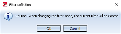
Drawing > Save/Print > Save as > 3-D formats (STEP, ...) 
You use this function to export HiCAD model drawings into the IFC format or as a packed IFC file into the IFCZIP format. To do this, select the required file type.
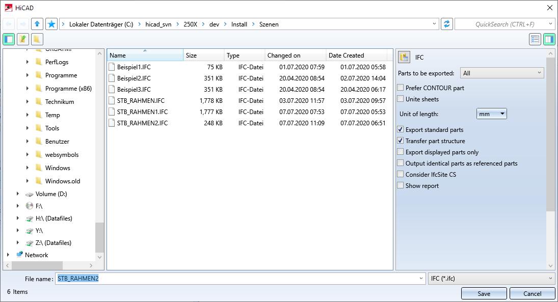
On the right hand side of the dialogue window the following options are available:
symbol - the part type. All parts filters defined with the Search via toolbar (Part filter)  function are supported. The following part filters are already predefined:
 | Industry | Part type | |
|---|---|---|
|
General
|
Referenced part |
|
|
Sketch |
|
|
|
Solid |
|
|
|
Plant Engineering
|
Straight pipe |
|
|
Elbow |
|
|
|
Pipeline |
|
|
|
Sheet Metal |
Sheet |
|
|
Mechanical Engineering |
Standard part |
|
|
Steel Engineering
|
Facade assembly |
|
|
Steel Engineering assembly |
|
|
|
General part |
|
|
|
Facade part |
|
|
|
Steel Engineering part |
|
|
Example:
A Cross-bracing (2602) has been installed between four beams. Cross-bracing was chosen as usage for the beams in the cross-bracing dialogue.
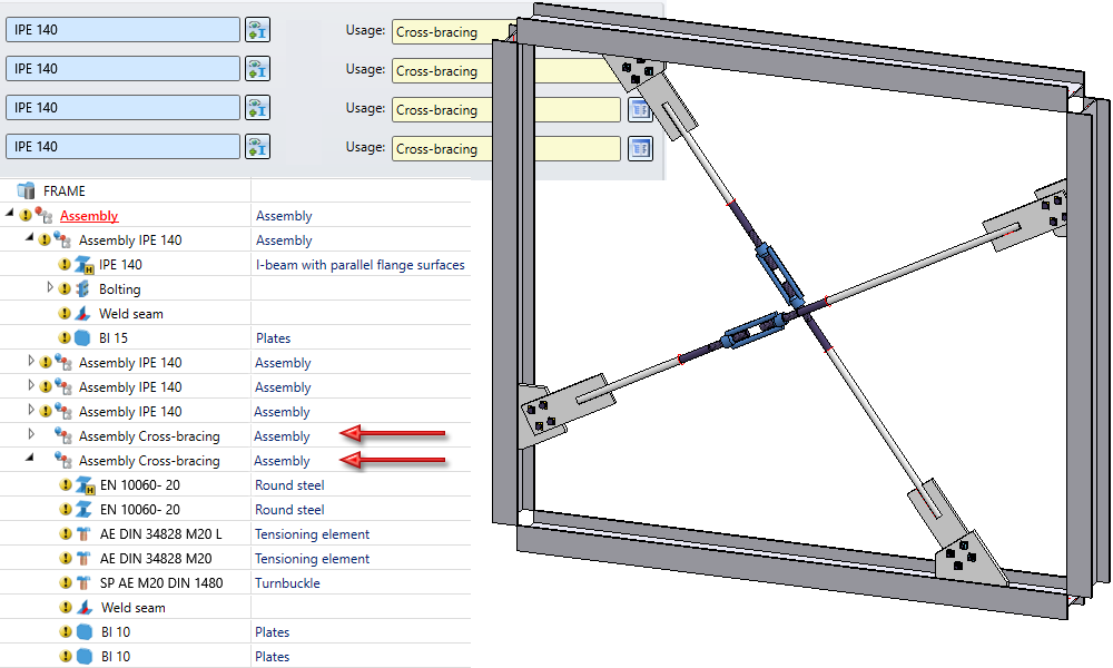
The two marked assemblies then have the usage Cross-bracing. If the model drawing is exported as an IFC file using the part filter Steel Engineering > Steel Engineering assembly > Cross-bracing, the parts of the assemblies will be combined into one part each.

![]() Please note:
Please note:
 symbol.

Steel Engineering Interfaces • Interfaces
|
© Copyright 1994-2020, ISD Software und Systeme GmbH |
Data protection • Terms and Conditions • Cookies • Contact • Legal notes and Disclaimer


 symbol.