Use of Variables
In complex drawings, it can sometimes becomes difficult to keep track of where a part variable is used. In such situations, the Use of variables function is very helpful.
You can access the function in two different ways:
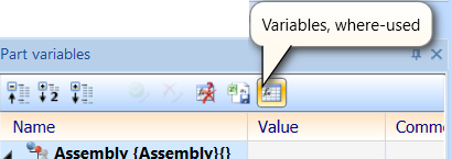
- In the Part variables docking window, the Variables, where-used button is located on the toolbar.
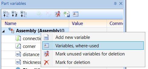
- If you right-click an entry of a part (or an assembly) in the Part variables docking window, the Variables, where-used entry can be found in the context menu.
The Use of variables dialogue window always refers to the part that was selected in the Part variables docking window when the dialogue window was opened. If a variable was selected here, the part containing this variable will be used.
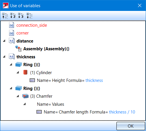
The Use of variables window lists in the first level all variables assigned to the selected part.
The icon in front of the variable indicates the type of the variable (e.g. Number, Edge). Unused variables are displayed in red.
The other variables can be expanded by clicking on the arrow in front of the variable and then show where the respective variable is used. For each usage, an entry is then displayed showing the part that uses this variable. In the image above, the distance variable is used in the assembly called "Assembly". This usually indicates that an HCM condition exists in the assembly that uses this variable.
The thickness variable is used twice by the "Ring" part. The entries can be expanded further to indicate that the variable is used here in certain features and also which parameters of the respective features use this variable. Formulas that use the variable are displayed in blue.

