Plant Engineering > Isometry/Pipe Spool Drawing> Isom...
Isometry + Pipe Spool Drawing > Create > New 
For eccentrically inserted pipes, there are two common special cases supported in isometric drawings and pipe spool drawings, namely
- top-of-pipe and
- bottom-of-pipe.
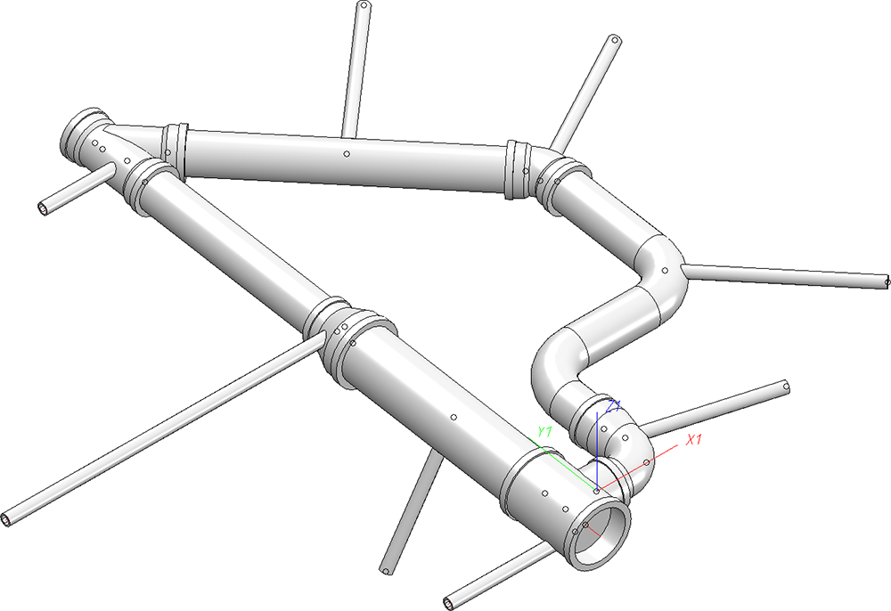
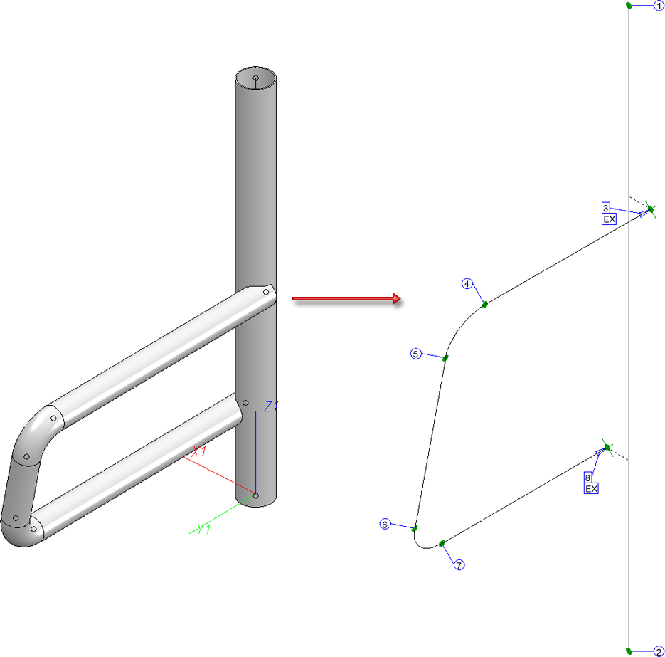
For example, let's take a look at the following model drawing:
If an isometric drawing or a pipe plan with connection symbols and numbers is created here, the result will look like this, for example:
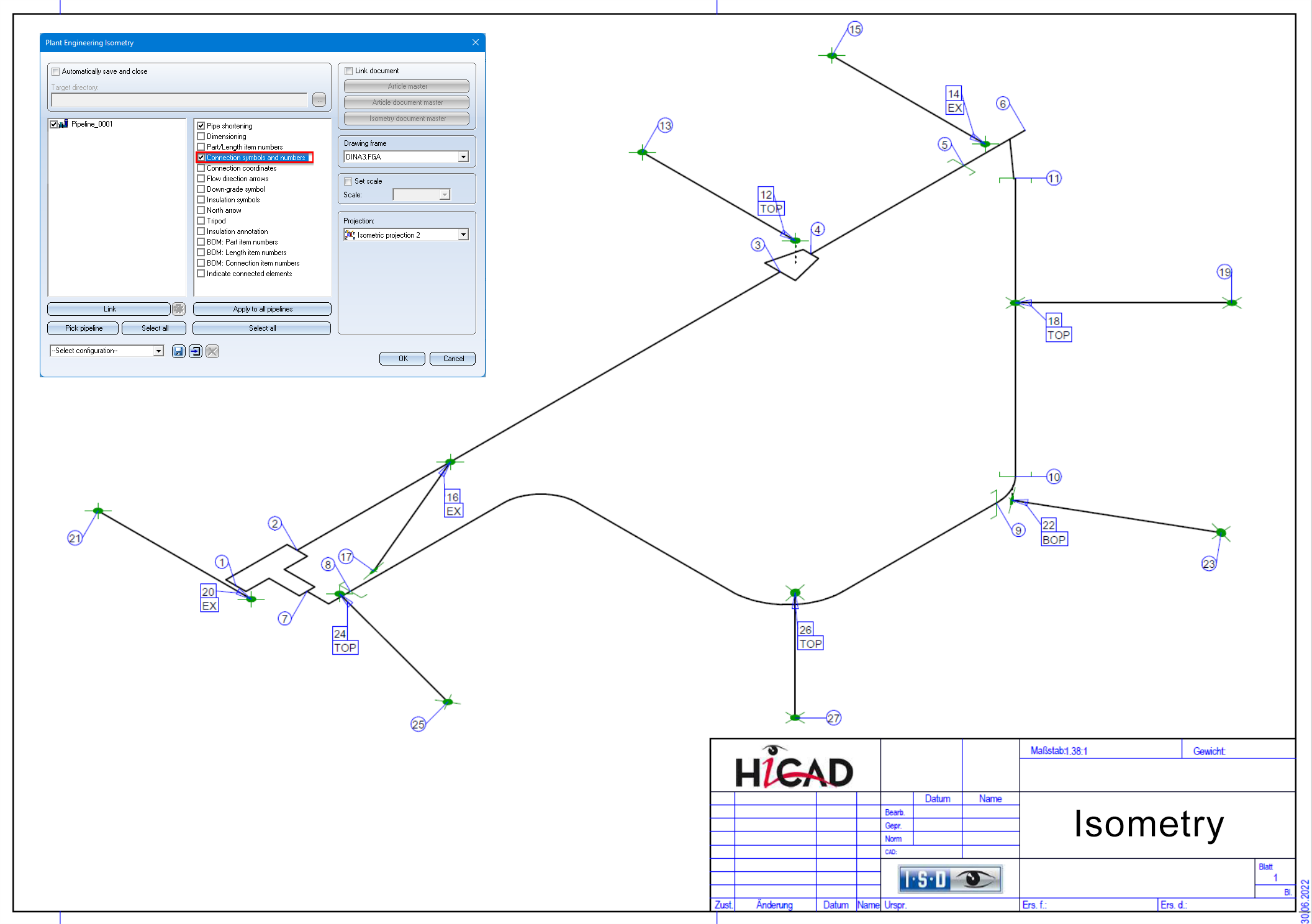
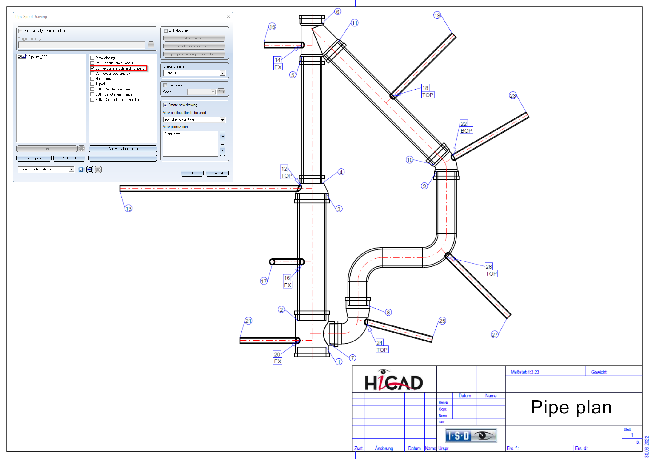
As you can see, for inserted eccentric pipes, the additional texts TOP, BOP und EX are output at the connection numbers, if applicable. This is the default setting for connections that are plugged in:
- top-of-pipe (TOP),
- bottom-of-pipe (BOP) or
- otherwise eccentric (EX)
You can customize this representation by modifying the corresponding FTD files:
- ISD_inserted_top.ftd,
- ISD_inserted_bop.ftd and
- ISD_inserted_ex.ftd.
Especially if you want to have the concrete coordinates displayed at such points, these three text objects have to be adapted.
![]() Please note:
Please note:
- The identification of top-of-pipe or bottom-of-pipe is only carried out for parts without a branch. Therefore, only EX can be read in the drawings above at the branch and T-piece.
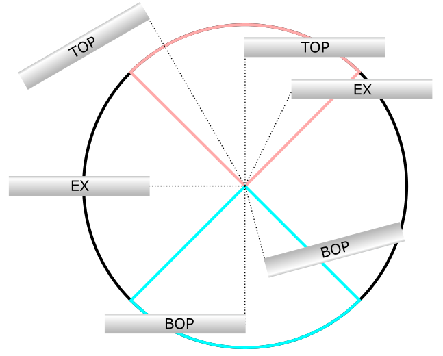
- A connection is only classified as top-of-pipe if the inserted pipe leads tangentially out of the thicker pipe and the connection is in the upper area of the thicker pipe. What the top area is depends on the coordinate system of the isometric drawing. The same applies to the classification as bottom-of-pipe. The following diagram shows this graphically:
- For pipes that are inserted into straight pipes, the isometry tries to draw the insertion points to the centreline as much as possible (assuming that pipe shortening is active). It may be that the geometry of the pipe prevents this. In such cases, dashed auxiliary lines are inserted.


Generate Isometry / Pipe Spool Drawing (PE/Iso) • Isometry and Pipe Spool Drawing (PE/Iso) • Isometry/Pipe Spool Drawing Functions for the Layout Plan