Steel Engineering - What's New

Service Pack 2 2022 (V 2702)
Divide beam
From HiCAD 2021 onwards, the Divide along direction  function is available for dividing beams + profiles. This function covers all Divide functions available until then. For this reason, these functions are no longer available as of HiCAD 2022 SP2. This means in detail:
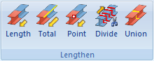
- The function Divide along direction replaces the previous function Divide in the Steel Engineering Ribbon in the function group Lengthen
 .
.
- The following functions are no longer available:
-
Divide
-
 Divide beam once, flush, with clearance
 -
 Divide beam several times, flush
 -
 Divide beam several times, flush, with clearance
This also applies to the context menus.
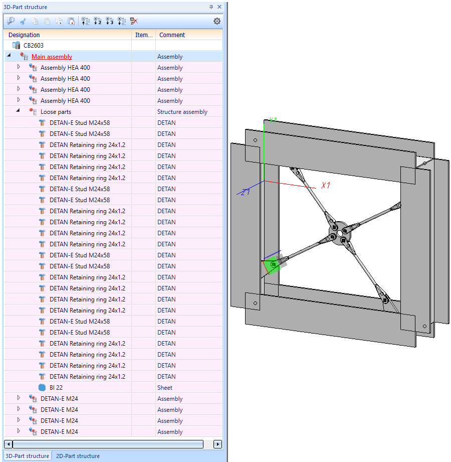
Cross-bracing (2603)
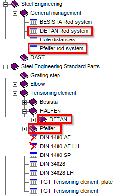
From SP2 onwards, the Cross-bracing (2603) Design Variant supports BESISTA tension rod systems as well as
DETAN and
Pfeifer
tension rod systems. The HiCAD catalogues Steel Engineering Standard Parts > Tensioning element and Steel Engineering > General management have been extended accordingly.
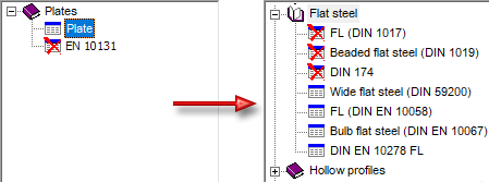
Strap joint (2310)
Semi-finished product for strap
From SP2 onwards, flat steels can also be selected as a semi-finished product for the Strap joint (2310) .
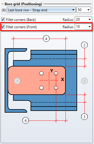
Fillets on welded corners of straps
From SP2 onwards, straps can also be filleted on the welded side in order to take into account the rolling radii of the beam passing through. The Strap tab has been extended accordingly..
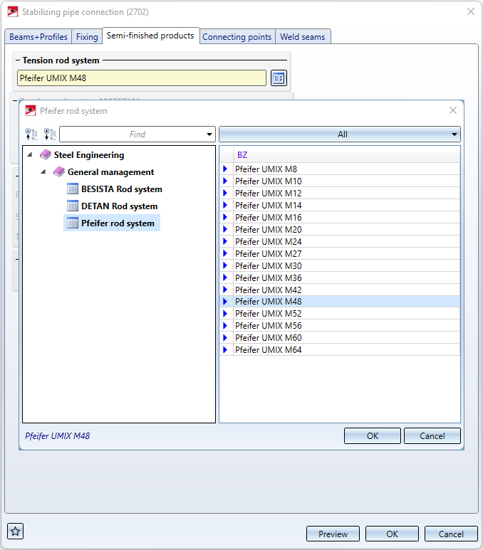
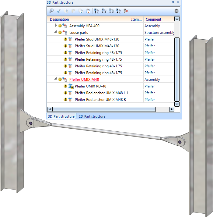
Stabilizing pipe connection (2702)
In addition to the BESISTA tension rod systems, DETAN and Pfeifer tension rod systems can now also be used for the Stabilizing pipe connection (2702).
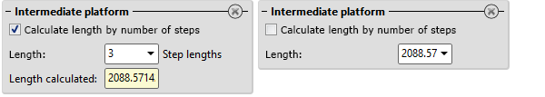
Staircase Configurator - Intermediate platforms
In the Staircase Configurator, it is now possible to specify for intermediate platforms whether the length of the platform is to be calculated by the number of steps or by entering a value. The checkbox Calculate length by number of steps is available for this purpose. If the checkbox is active (default setting), the length is automatically calculated and displayed after entering the number of steps. This value cannot be edited. If the checkbox is not active, you can determine the length by entering a value.
Service Pack 1 2022 (V 2701)
Steel Engineering settings - Default Material
The selection of the default material is no longer available on the Weight calculation tab of the Steel Engineering settings  function. The previous setting was only used for the following functions:
- Prototype beam
 ,
, - Beam from sketch
 and
and - when importing steel engineering plates via the SDNF interface. Here, the default material was only used (and the plates were only imported/generated) if a plate also existed for the selected default material in the catalogue table Semi-finished products > Plates > Plate.
S235JRG2 is now used as the default material. For the functions Prototype beam and Beam from sketch this applies to the first call within a HiCAD work session, for further calls of the function the last selected material is preset.
Also, the setting "Steel Engineering > Default material" is no longer available in the Configuration Editor.
Connections
Clamping plate
As of SP1, Lindapter girder clamps of type A, B and D2 are also available for fastening clamping plates.
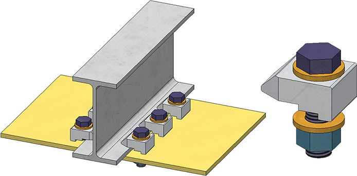
Lindapter girder clamp Type D2
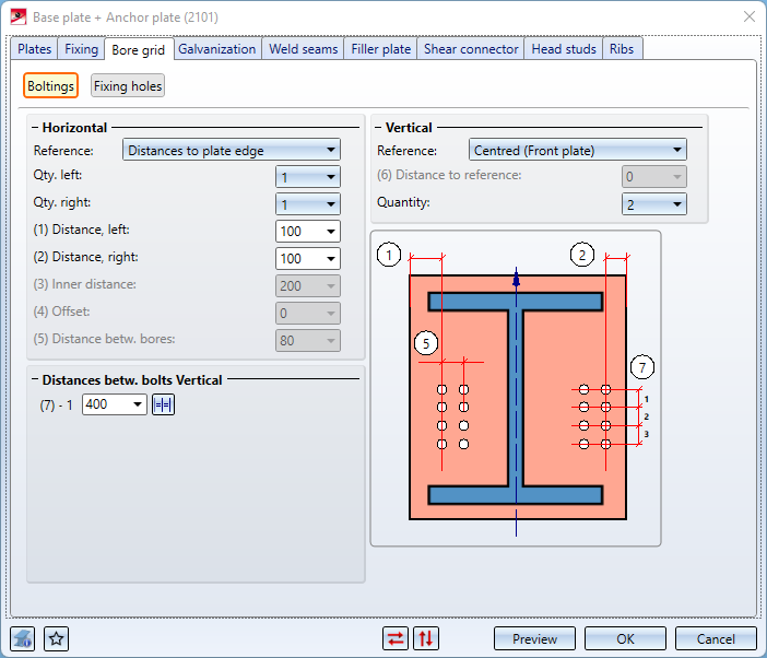
Base plate + anchor plate (2101)
The Bore grid tab has been divided into the following sections:
- Boltings
Here the arrangement of the bolting, the hole pattern or the threaded studs on the plate is defined.
- Fixing holes
Here you determine whether additional fixing holes are to be created that are independent of the bolting. In practice, these are sometimes needed, for example, to temporarily fix the base plate with nails when mounting the column. In this case, determine the diameter of these holes and their horizontal and vertical distance from each other.
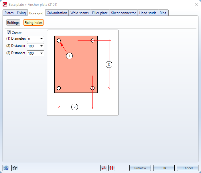
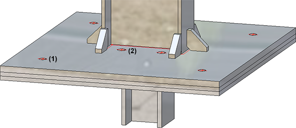
(1) Bores for the boltings, (2) Fixiing holes
Strap joint (2310)
If the connection type With stiffener is selected for the strap joint, the Galvanization tab is also available.
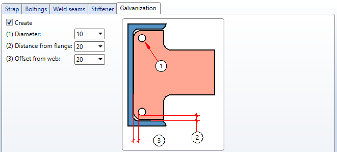
Here you determine whether the stiffeners are to be provided with holes for galvanization. Activate the corresponding checkboxes and enter the desired diameter. In addition, you can specify the minimum distance of the holes to the flange and to the web.
Railing Configurator
Determining the railing route
The determination of the railing route in HiCAD 2022 SP1 has changed as follows:
- First, the beam end where the railing should start is selected.
- Then the beam end must be selected that determines the direction in which the railing will be installed.
If the order of the selected beams results in only one possible walking line of the railing, then the selection of the end of a beam is ignored.
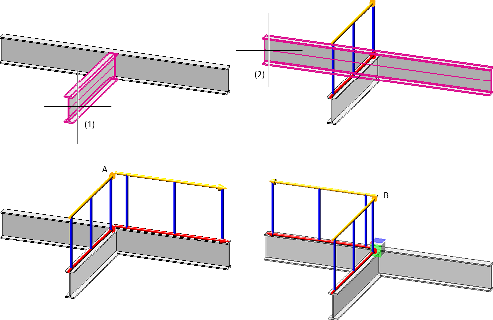
In the example shown below, the first beam is selected at point (1), the second beam at point (2). A shows the result before HiCAD 2022 SP1, B the result in HiCAD 2022 SP1.
Infill with knee rails
For infills with knee rails, the "Trim to posts" checkbox on the Infill tab has been replaced by a selection box.
The additional option Trim to front edge of post is also here. This corresponds to the function Trim, to outer edge.
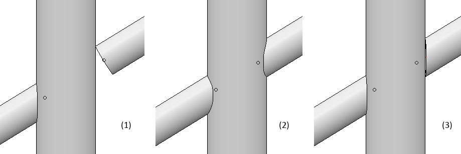
(1) Do not trim, (2) Trim to post, (3) Trim to front edge of post
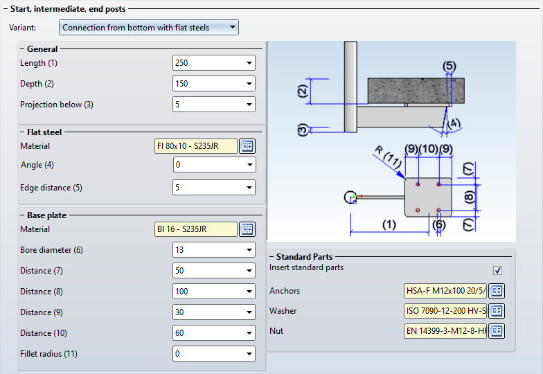
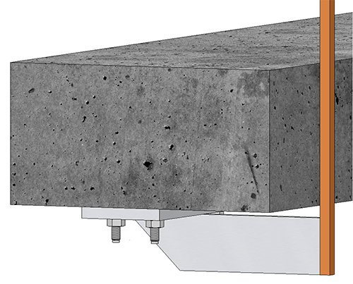
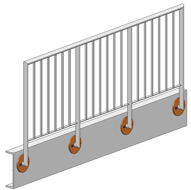
Post - Sub-structure - Connection from bottom with flat steels
On the Post-Sub-structure tab, an additional connection variant is available as of HiCAD 2022 SP1: Connection from bottom with flat steels.
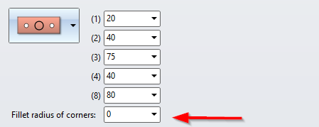
Post-Sub-structure - filleted and round base plates
The corners of rectangular base plates can now also be filleted. The new input field Fillet radius of corners is available for this purpose.
In addition to rectangular base plates, round base plates can now also be used.
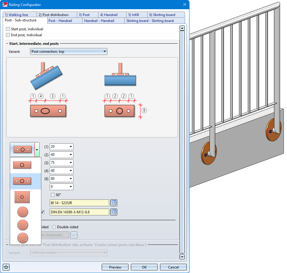
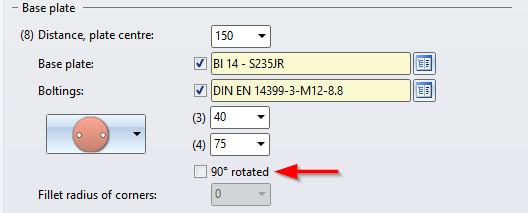
Post-Sub-structure - Base plates rotated 90°
If the bore with 2 holes is selected for rectangular or round base plates, it is possible to rotate the base plate 90° from HiCAD 2022 SP1.
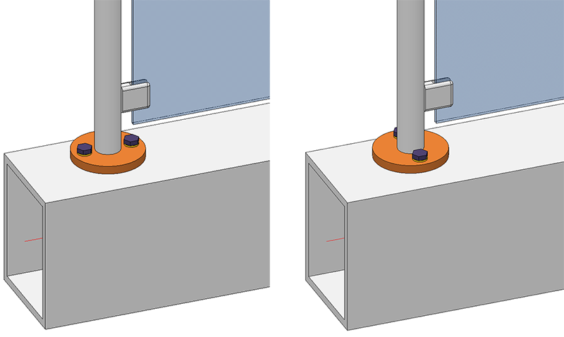
Post-Sub-structure -- Lateral connection with penetration of base plate
If the connection is made with a distance element, there is now a possibility that the distance element penetrates the base plate when connecting laterally. To do this, activate the checkbox Penetration of base plate and specify the Clearance, the Corner radius and the Offset.
(1) Base plate, (2) Distance element, (3) Clearance, (4) Offset, (5) Corner radius
Handrail on wall
With the Railing Configurator, handrails with wall consoles can now also be created. For this purpose, the tab Post - Handrail has been extended by corresponding variants.
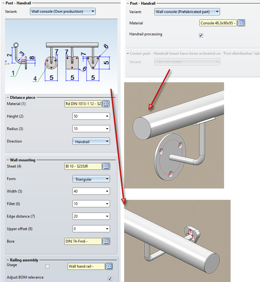
To create the wall console you must set the
- Posts,
- Infills and
- Post - Substructure constructions
to Do not create / Do not insert. In addition, a lateral offset to the handrail must be entered on the Post tab.
Major Release 2022 (V 2700)
Connections / Design Variants
Clamping plate
New in the Civil Engineering functions docking window at Steel Engineering > General is the clamping plate function. Clamping plates are used when parts are not to be screwed or welded. The following connections are possible:
- One plate between two beams
The clamping plates are bolted to the plate. - One beam and one plate
The clamping plates are bolted to the plate. - Two beams
The clamping plates are bolted to the second beam.
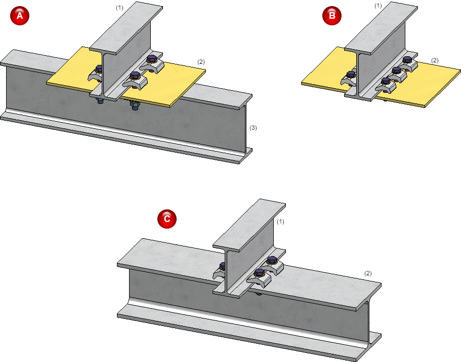
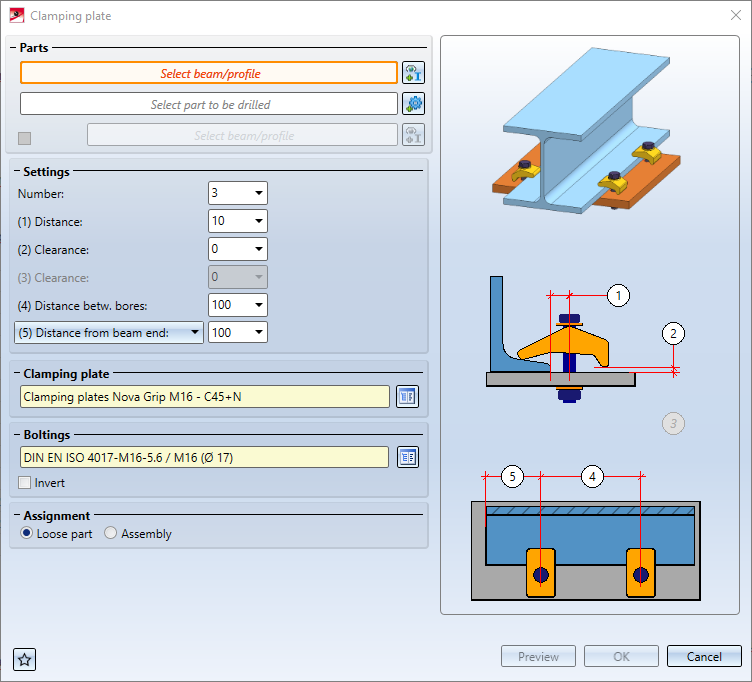
(A) Plate between 2 beams, the plate is drilled; (B) Beam and plate, the plate is drilled; (C) 2 beams, the 2nd beam is drilled
After calling the function, theClamping platedialogue window is displayed.
Zinc plating holes for galvanisation
From HiCAD 2022 onwards, only one of the zinc plating holes for galvanisation will be annotated in the workshop drawings, and not each zinc plating hole as before. This applies to the following connections:
- Beam to web with 2 plates and stiffener (1211),
-
Purlin joint, 2 plates with mitre cut acc. to DAST IH (2201),
Please note however that this principle only applies to zinc plating holes on beams, not on plates.
Create detail drawing
With HiCAD 2012, the previously valid functionality for creating Steel Engineering workshop drawings has been expanded to a function for general drawing derivation. For reasons of compatibility, the previously available functions for Steel Engineering detail drawings continued to be available at Drawing > Itemisation/Detailing > Derive  > ... were still available. As of HiCAD 2022 (V 2700.0) the former functions for creating detail drawings are no longer supported:
|
|
Create detail drawing |
|
|
Create + print detail drawing |


Use the automatism for workshop drawings to create detail drawings.
However, the remaining functions are still useful for old model drawings in some cases. Therefore, these functions are available at Drawing > Itemisation/Detailing > Derive... > Detail drawing - Up to HiCAD 2021 in a separate sub-menu.
Sectional views with Steel Engineering plates
As with Sheet Metal parts, from HiCAD 2022 it is also possible to specify for Steel Engineering plates whether the coating is to be marked in the sectional view or not. The marking is done by an offset edge, the so-called coating line. The settings defined in the Configuration Editor at Drawing > Annotations > Coating line in sectional view are used to display the coating line.
The display of the coating line of Steel Engineering plates can also be changed subsequently. To do this, right-click on the coating line in the corresponding view and activate the desired function in the Coating symbol context menu.
In addition, the representation of the coating lines can also be changed via the context menu for Steel Engineering plates s if a sectional view is active. To do this, right-click on the plate in the sectional view and then select Properties > Coating line.
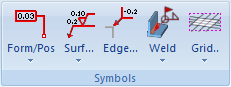
Grid annotation
From HiCAD 2022 onwards the functions for grid annotation can be found at 3-D Dimensioning+Text > Symbols > Grid.