Insert Beams
Steel Engineering > New
Various options are available for the insertion of beams:
- Using the integrated expert system for the insertion of standard beams. It provides, for example, a large selection of 3-D standard beams.
- Using series created from 2-D contours or 2-D variants.
- Deriving beams from a sketch.
- Applying the cross-section of an arbitrary beam in the drawing for a new beam.
- Using bar elements when you want to create only a first, rough draft.
You can insert beams either as main parts or sub-parts.
|
Beam insertion functions, for main parts |
|
|---|---|
|
|
Inserts 3-D standard beams according to DIN. |
|
|
Inserts prototype beams (beams with predefined geometry and variable sizes). |
|
|
Derives beams from a sketch. |
|
|
Applies the cross-section of an existing beams. |
|
|
Inserts user-defined beams via selection from factory standard catalogues. |
|
|
Inserts user-defined beams by selection via Explorer. |
|
|
Insert series, via DB document master Inserts user-defined beams via document master data. |
|
|
Insert series, via DB article master Inserts user-defined beams via article attributes. |
Click  to open a pull-down menu with further functions for the insertion of beams and options for sub-parts.
|
|
Inserts multi-part standard beams, such as double L-beams, welded beams or box beams. |
|
|
Inserts elongated plates. |
|
|
Inserts bar elements, e.g. for rough drafts and concepts. |
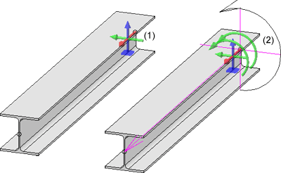
Indication of beam orientation
When you insert a Steel Engineering beam, the orientation of the beam, i.e. the
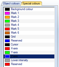
- axis direction (in the Special colour X-axis)
- top/bottom (in the Special colour Z-axis),
- left/right (in the Special colour Y-axis),
- rotation axis
will be indicated in the form of a coordinate system at its start. The indication appears as soon as the beam becomes visible, and its position still need to be specified.
The indication of orientation can be set in the Configuration Editor, at ... > System settings > Visualisation > Indicate orientation of active Steel Engineering beam. The following options are available:
- Only upon insertion
The orientation of the beams will only be indicated when they are inserted. This is the default setting. - Always
The orientation will always be indicated (if set). - Switch on/off with F6 key
The indication of the orientation can be switched on or off with the F6 key. Alternatively, you can also use the
 Show beam orientation or drawing alignment of the active 3-D part [on/off] symbol on the Coordinate systems toolbar (at the bottom of the dialogue window) for this.
Please note that the size of the orientation symbol will not change when you zoom in or out.

(1) During activation, (2) During insertion
The colours of the orientation symbol can be changed via the Colour Editor  (Drawing > Others > Colour Editor).

![]() Please note:
Please note:
- Irrespective of the selected insertion function, the Insertion options are always displayed if HiCAD asks you to specify the fitting point.
- If you right-click in an input field of the Insertion options menu bar, a context menu opens. You can use the functions of this menu to transfer angles and lengths from existing drawing objects to the input field. For example, the Pick distance function enables you to transfer a beam length from the drawing. If you would like to transfer the rotation angle for the beam, you use the Pick angle function .
- HiCAD allows you to work with a "dynamic" zoom window. You can use F2 to activate this zoom window at any time within a function. The area in which the cursor is currently positioned is then displayed in a window, considerably enlarged. This enables you, for example, to define the fitting point of a beam more easily in complex drawings, without having to specify a new screen display before processing. Once you have defined the point, you can use F2 or ESC to hide the window again.
- Beams are frequently located in the same plane, e.g. for stages, bridge frames, substructures for car parks, roof constructions etc. In this case, you should leave the Insert beam in space and Insert beam perpendicular to processing plane options deactivated and, instead, fit the beams using a steel engineering auxiliary line grid. When defining the start and end points, you can then access the grid points directly, which speeds up fitting.
- The functions for fitting beams remain active after fitting a beam. This means that you can immediately insert more beams of the selected type. Press the ESC key or the middle mouse button to end the function.
- When inserting catalogue standard parts and semi-finished products (Steel Eng. beams/profiles, plates) in HiCAD, values from the catalogue item are assigned to some part attributes of the HiCAD part (e.g. the "BZ" column is assigned to the "Attribute number" part attribute ). This process is freely configurable.
In the catalogue tables you have the option to link a table column to a part attribute. When inserting a part from this table in HiCAD, the value of the linked column will then be assigned to the part. A user can, for instance, enter the article number and/or the supplier in a column, and the value will be assigned to a part attribute when inserting a part and can subsequently be used for part annotations or bills of materials. In the catalogue table (see Catalogue Editor)linked columns are identified by a link symbol in the column header. From version 2008 onwards, the "BZ" columns of tables for standard parts and semi-finished products are linked to the part attribute "$BB"; "CUSTOM1" columns are linked to the part attribute "CUSTOM1", and "CUSTOM2" columns are linked to the part attribute "CUSTOM2".

Insertion Options for Beams (3-D SE) • Steel Engineering Functions • General Information (3-D SE)


