Assembly HCM: General Information
The Assembly HCM offers a technique that allows the parameterization of model drawings. Individual parts are combined by
- Positional constraints and
- Dimensional constraints
into complex assemblies. The Assembly HCM then transforms the parts so that the specified conditions are met.
However, it is not only these elements, but the entire assembly that is transformed. The HCM models are not calculated immediately upon loading a construction, but only when an HCM model is accessed.
You may also activate the Part HCM Selection context menu with a right click to select the reference geometries. The context menu offers (besides some other functions such as Hide surface) the following options:
| Part HCM Options | |
|
Geometry |
Selection by identification of the required geometry |
|
Select surface |
Selection of a surface. |
|
X-, Y- or Z-Axis |
Selection of the X-, Y- or Z-axis. |
|
XY-, XZ- or YZ-Plane |
Selection of the XY-, XZ or YZ-plane |
![]() Please note:
Please note:
- Please note that you can only assign constraints to complete parts. You cannot use the Assembly HCM to move individual edges or surfaces and hence to distort a part.
- Constraints are always assigned between elements of different units, e.g. between the top surface of a cuboid and the base surface of a cylinder. Other types such as toruses, freeform surfaces etc. may, however, be contained as elements in the parts, as long as they are not meant to be used as a reference for a constraint.
- Assembly HCM models can be stored as a variant and reused at any time. This enables you to systematically capture and automate many construction tasks.
- If geometric changes are made to a part containing HCM constraints, the constraints are checked and updated after the changes.
In addition to the assignment of constraints and the associated position of the parts, the Dragger is one of the most important components of the Assembly HCM. It allows you to use the mouse to move individual parts while complying with already assigned constraints. This enables you to perform dynamic manipulations even on complex models, i.e. spatial movements are controllable and are visualised in real time.

The importance of the part structure
When assigning constraints, the part structure and hence the arrangement of the parts is crucial.
You can assign constraints only within a main assembly and only to parts of an active body.
If, for example, you activate a main part with sub-parts, HiCAD regards the sub-parts of a hierarchy as one unit. No constraints can be assigned within this unit.
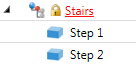
In the 3-D part structure, part containing dimensional or positional constraints are indicated by a lock symbol next to the symbol of the part.
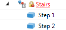
In the Configuration Editor at System settings > Assembly HCM you find the setting option Show HCM errors in part structure?. This function is deactivated by default. If you activate this option, inconsistent HCM models in assemblies will be marked in the 3-D structure with a corresponding symbol.
In this case a red exclamation mark can be found on the lock symbol. This marking will also be applied to superordinate parts and assemblies to indicate the inconsistencies up to the top level of the affected element:
 Please note:
- The Drag function moves, if you have activated an assembly, immediate sub-parts. For an assembly, which in turn contains assemblies, the Dragger therefore moves the contained assemblies as a whole, not individual parts of them. If you want to drag sub-parts of an assembly, first activate the corresponding assembly.
- The HCM tab of the ICN lists the constraints for all parts of the active assembly. The first line lists whether the HCM model is fully defined or under-defined. In the latter case, the number of degrees of freedom is additionally displayed. For the individual constraints, HiCAD also indicates if there is an under-definition of the element. Also, you have the option to deactivate individual HCM constraints manually or depending on variables. For further information, please read the information given in the The HCM Window in the ICN topic.
- If you select an HCM constraint in the ICN, the elements that belong to this constraint are marked in the drawing. This marking is also preserved when views are rotated. Relevant surfaces of a constraint are marked in green. This default setting (mark_faces=1) is saved in kzugpar.dat in the SYS directory.
- Right-clicking in the window enables you to switch between sorting by geometries and sorting by constraints. You can use the context menu of a set constraint to change or delete the constraint.
