
Project: HiCAD Metal Engineering
"Civil Engineering functions" docking window > Civil Engineering, general > Detail and section planning > Foil
This function places a foil along a composite edge from a sketch.
After calling the function in the Civil Engineering functions docking window at Civil Engineering, general > Detail and section planning > Foil, the Foil dialogue window opens:
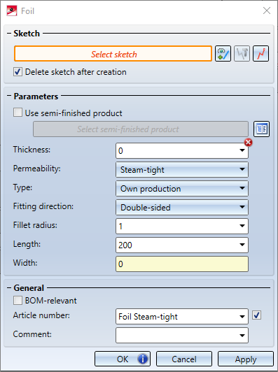
The dialogue window consists of the following areas:

In the Sketch area, you can select the sketch to be used as the basis for the new foil. This function is active by default after calling the dialogue as long as an existing sketch was not active in the drawing. In this case the existing sketch is used.
The displayed buttons offer you the following options:
 Select sketch: After activating this button you can select an existing sketch in the model drawing.
  Process sketch: If a sketch is selected, you can modify it by clicking this button.
  New sketch in plane: Creates a new sketch in the model drawing and allows you to edit it directly.
 If the Delete sketch after creation checkbox is activated, the sketch used will be deleted after the foil is created.
In the Parameters area you can define the parameters for the foil to be created.
If you activate the Use semi-finished product checkbox, you can select a semi-finished product from the catalogue in the Select semi-finished product field below. These are taken from the path Factory standards > Foils. The Thickness, Permeability and Type fields are then filled with the values of the semi-finished product and can no longer be changed manually. In addition, the name of the semi-finished product is entered as an Article number for the created foil and it is checked that the Width of the foil is not greater than the width required for the selected composite edge.
The Thickness value defines the thickness of the foil to be created.
In the Permeability field you can choose between Steam-tight and Steam-permeable.
In the Type field you can choose between Available on site (mortar, concrete) and Own production.
The Fitting direction determines how the foil is to be placed in the Z-direction of the sketch. Double-sided places the centre of the foil on the sketch. So one half is "in front" and one half is "behind" the sketch. -Z places the foil completely behind the sketch, +Z places it completely in front of the sketch. When an option is selected, a preview of the created foil is displayed in the design.
Fillet radius defines the radius used to create the foil at corners of the sketch to simulate a bend of the foil around that corner.
Length defines the length of the foil in Z-direction.
The value in the Width field cannot be changed, but specifies the calculated width of the created foil. This value includes the fillet radius at corners in the sketch.
In the General section you have the possibility to set the generated foil as BOM-relevant and also to assign any Comment for this part.
After clicking on OK the desired slide is created. If the generation cannot be carried out, a hint symbol will be displayed on the button. If you move the mouse over this icon, a description of the error is displayed.

|
© Copyright 1994-2021, ISD Software und Systeme GmbH |
Data protection • Terms and Conditions • Cookies • Contact • Legal notes and Disclaimer