3-D Standard > Process with sketch > Subt. > Divide
With this function you divide a part based on a planar sketch. Each line of the sketch is a section line that divides the part into two section regions. Connected lines are treated as one line. This means, for example, that a sketch consisting of three connected lines also divides a part into two cutting regions. Each cutting region can consist of several sections, whereby the number of sections is determined by the actual number of lines.
The following image shows parts thate have been divided with a clearance - a cylinder, a cuboid and a sheet metal part.
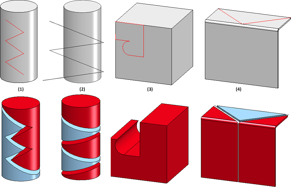
(1) The sketch consists of five connected lines, none of which extend beyond the part. This results in two cutting regions and thus two segments.
(2) Here the sketch extends beyond the edge of the cylinder. However, there are also only two parts, but they consist of several parts.
(3) The sketch is closed and two sketch lines lie exactly on the edges of the cuboid. In this case, one area of the cuboid is cut away completely and no additional part is created. (In this case, a material subtraction would also have led to the goal).
(4) (4) Two parts are created, whereby the red part consists of two segments.
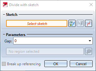
After calling the function, the Divide with sketch dialogue window is displayed.
Proceed as follows:
- Select a sketch for the division of the part. You have the following options:
|
|
Select sketch Click on the icon to select another sketch subsequently. After calling up the function, the sketch can also be selected directly in your drawing. |
|
|
Process sketch This function allows you to modify a previously selected sketch. Then change the sketch as desired and click Apply sketch in the dialogue window. The dialogue will continue with the modified sketch. |
|
|
New sketch in plane With this function you can create a new sketch that will be used to create the solid. Create the desired sketch and then click Apply sketch. The dialogue continues with the new sketch. |


After selecting the sketch, a preview of the division is displayed immediately.
- If desired, specify a Gap under Parameters. The preview is updated automatically.
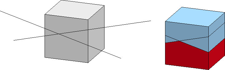
- One of the resulting parts is highlighted red in the preview. This part is the "leading part" and is automatically determined by HiCAD. The corresponding cutting region is named region 0. This part can consist of several segments. This depends on whether the sketch lines are connected or not.
If you want to select another part as the leading part, click on the  symbol and select the part. In the preview the colour of the parts changes.
-
If the original part is referenced, the referencing can be broken up by deactivating the checkbox. When breaking up, an existing HELiOS document and article master at the original part is also deleted. If the checkbox is active, the referencing is assigned to the leading part. This also applies to a HELiOS document/article master existing at the starting part - the other parts created are not referenced.
Click OK to execute the function and then close it. If you click on Apply, the dialogue remains open.
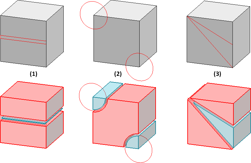
Example 1:
The image shows a cuboid with three different sketches and the resulting division. In all cases, two parts are created. In (1) and (3) the "leading part" consists of two segments, in case (2) of one segment.
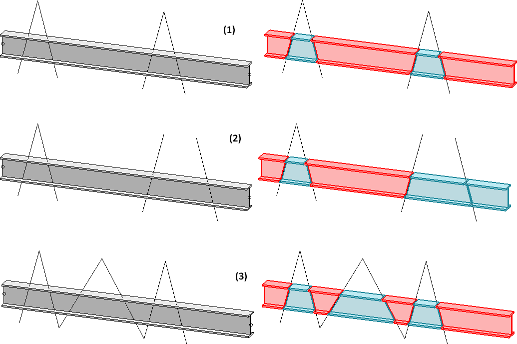
Example 2:
The following image shows a divided profile.
(1) Three parts are created, whereby the red part consists of three segments.
(2) Four parts are created, whereby the red component consists of two segments.
(3) Two parts with four (red) and three (blue) segments are produced.
The "leading part" (marked red when the function is executed) is assigned the main feature Divide with sketch. With this feature the sketch can be edited later and the gap can be changed. All other created parts are assigned the feature from division.
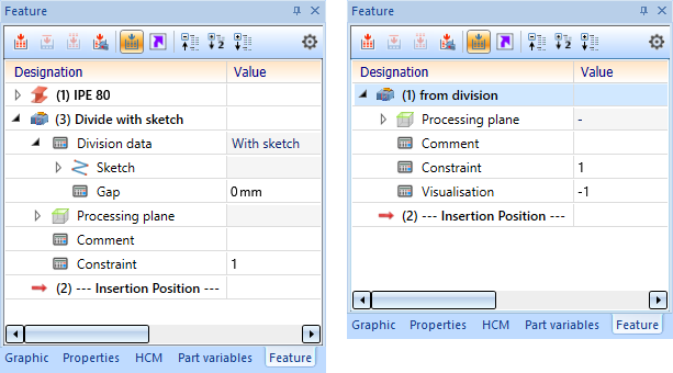
Double-click on one of the features to start the dialogue.
Note:
If the sketch region for the main feature cannot be found again, this is documented as an error on the feature.
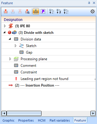
Possible reasons for the omission of the main feature region are:
- The region is deleted from the sketch
- The section is empty
![]() Please note:
Please note:
- Alternatively, you can call the function via the context menu for parts.
- Sub-parts are not considered in the function. Sheet metal parts are an exception.
- The sketch lines can also overlap.


Sketch Function (3-D) • The "Process with Sketch" Dialogue Window (3-D)